Doosan DX160LC-3 Excavator Service Manual
$35.00
Manual Included:
- Service Manual: 891 Pages
Specifications:
- Brand: Doosan Excavator
- Model: DX160LC-3
- Serial Number: 50001 and Up
- Type: Excavator
- Manuals: Service Manual
- Publication Number: 950106-01172E
- Language: English
- Format: PDF
- Description
- Reviews (0)
Description
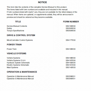
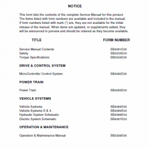
Table of Contents:-
Safety
Track Excavator Maintenance Safety……………………………………………SP002322
Specifications
Specifications for DX160LC-3………………………………………………………SP002509
General Maintenance
General Maintenance Instructions………………………………………………..SP002454
Standard Torques………………………………………………………………………SP002404
Upper Structure
Cabin……………………………………………………………………………………….SP002324
Counterweight……………………………………………………………………………SP002510
Fuel Tank………………………………………………………………………………….SP002511
Fuel Transfer Pump (Option)……………………………………………………….SP002546
Swing Bearing……………………………………………………………………………SP002329
Swing Reduction Gear………………………………………………………………..SP002526
Lower Structure and Chassis
Track Assembly…………………………………………………………………………SP002524
Engine and Drivetrain
Engine Coolant Heater (Option)…………………………………………………..SP002328
Drive Coupling (Main Pump)………………………………………………………..SP002515
Hydraulics
Hydraulic System Troubleshooting, Testing and Adjustment……………SP002538
Accumulator………………………………………………………………………………SP002455
Center Joint (Swivel)…………………………………………………………………..SP002456
Cylinders………………………………………………………………………………….. SP002539
Swing Motor………………………………………………………………………………SP002527
Travel Device…………………………………………………………………………….SP002514
Main Pump………………………………………………………………………………..SP002517
Gear Pump……………………………………………………………………………….SP002500
Main Control Valve…………………………………………………………………….SP002528
Remote Control Valve (Work Lever / Joystick)……………………………….SP002395
Travel Control Valve (with Damper)………………………………………………SP002381
Solenoid Valve Assembly……………………………………………………………SP002406
Breaker EPPR Valve (Option)……………………………………………………..SP002458
Dozer Valve………………………………………………………………………………SP002529
Hydraulic Schematic (DX160LC-3)……………………………………………….SP002518
Electrical System
Electrical System……………………………………………………………………….SP002337
Electrical Schematic…………………………………………………………………..SP002508
Attachments
Boom and Arm…………………………………………………………………………..SP002513
Bucket………………………………………………………………………………………SP002506
Doosan DX160LC-3 Manual Instruction Extract:
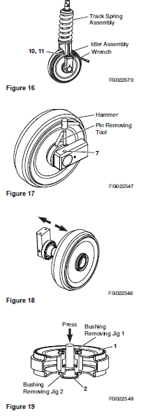
1.Detach T/Spring assembly from Idler assembly.
Remove 4-M16 bolts and washers (10 and 11, Figure 16).
2.Remove the plug (8, Figure 15) from the bearing (4, Figure 15) (using 6 mm “L” wrench).
NOTE: About 330 cc of oil will be discharged. Prepare
an oilcloth or pan to prevent spillage on the
ground.
3.Using a hammer and pin-removing tool, remove the pin (7, Figure 17) on one side.
4.Remove the bearing (4, Figure 15) on the side from which the pin (7, Figure 17) has been removed.
5.From the removed bearing (4, Figure 15) and front (1, Figure 15), separate the floating seal (5, Figure 15).
6.From the shaft (3, Figure 15), separate the O-ring (6, Figure 15).
NOTE: If the O-ring is not removed, the bearing
subassembly on the opposite side will be
difficult to separate
7.Separate the bearing subassembly on the opposite side of the front (1, Figure 15).
8.Separate the floating seal (5, Figure 15) from the separated bearing subassembly and front (1, Figure 15).
9.Separate the pin (7, Figure 15) from the separated bearing subassembly.
10.Separate the shaft (3, Figure 15) from the bearing (4, Figure 15).
11.Separate the O-ring (6, Figure 15) from the shaft (3, Figure 15).
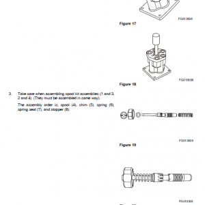
12.Separate the bushing (2, Figure 19) from the front (1, Figure 19).
NOTE: Insert jig 2, and press jig 1 to separate.
Use the hydraulic press for pressing the jig. Be
careful of sputtering.
13.Turn the front upside down. Separate the bushing (2, Figure 19) in the same manner as described above (Figure 19)
How to Use The Doosan DX160LC-3 Excavator Guide Manual:
This manual provides information for servicing the DX160LC-3 Doosan Excavator. All service procedures are broken down into detailed steps, listed in their recommended sequence. The manual uses both photographs and drawings to help locate and itemize components. The table of Contents on the preceding pages is your best tool for finding the service procedure you need. Be certain to observe all Safety information included in these pages.
A schematic of each of the major engine systems is provided at the beginning of the section of the manual devoted to troubleshooting and repairing that particular system.
Basic safety precautions are list in the Safety section of the Doosan DX160LC-3 Excavator Service Manual. Additional safety precautions are list in the Safety section of the owner/operation/maintenance publication. Specific safety warnings for all these publications are provided in the description of operations where hazards exist. WARNING labels have also been put on the product to provide instructions and to identify specific hazards.
Be the first to review “Doosan DX160LC-3 Excavator Service Manual”
You must be logged in to post a review.




Reviews
There are no reviews yet.