_1")
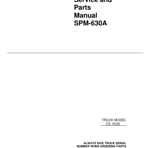
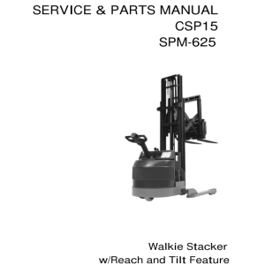
Clark CS15, CS20 Forklift Parts and Service Manual
$20.00
Format: PDF
Language: English
Machine Type: Forklift
Model Covered: CS15, CS20
Manual Type: Service Parts Manual
- Clark CS15, CS20 Forklift Service Parts Manual – 95 Pages
- Description
- Reviews (0)
Description
Clark CS15, CS20 Forklift Parts and Service Manual
Format: PDF
Language: English
Machine Type: Forklift
Model Covered: CS15, CS20
Manual Type: Service Parts Manual
- Clark CS15, CS20 Forklift Service Parts Manual – 95 Pages
Table of content of the Service Parts Manual
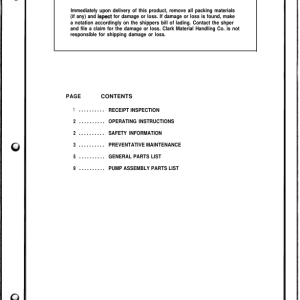
1. Receipt Inspection …………………………………………………………………………………………………………3
2. Pre-Operation Instructions……………………………………………………………………………………………….3
3. Safety Information………………………………………………………………………………………………………….4
4. Operating Instructions …………………………………………………………………………………………………….5
5. Control System……………………………………………………………………………………………………………..7
6. Battery Discharge Indicator (BDI) – Operation………………………………………………………………………9
6.1 Hourmeter ……………………………………………………………………………………………………………9
6.2 BDI and Hourmeter ………………………………………………………………………………………………10
6.3 BDI w/Lift Interlock……………………………………………………………………………………………….11
7. Drive Unit & Brake ……………………………………………………………………………………………………….12
8. Mast and Carriage ……………………………………………………………………………………………………….13
9. Hydraulic Adjustments ………………………………………………………………………………………………….13
9.1 Lifting Pressure …………………………………………………………………………………………………..13
9.2 Lowering Speed:………………………………………………………………………………………………….13
10. Planned Maintenance …………………………………………………………………………………………………..14
10.1 Lubrication Points ………………………………………………………………………………………………..15
10.2 Lubrication Points ………………………………………………………………………………………………..16
10.3 Lubrication Schedule ……………………………………………………………………………………………16
10.4 Battery Maintenance …………………………………………………………………………………………….17
10.5 Battery Cable Connections …………………………………………………………………………………….18
(for built-in battery / charger pack)
11. Trouble Shooting Guide ………………………………………………………………………………………………..19
12. Heavy Duty Stacker – Parts Listings …………………………………………………………………………………20
12.1 General Assembly Parts List…………………………………………………………………………………..22
12.2 Mast and Carriage Assembly – Single Stage ………………………………………………………………26
12.2.1 Cylinder Assembly – 3000 Single Stage…………………………………………………………28
12.2.2 Cylinder Assembly – 4000 Single Stage…………………………………………………………30
12.2.3 Crosshead Assembly – Single Stage …………………………………………………………….32
12.2.4 Chain Assembly – Single Stage……………………………………………………………………33
12.3 Mast and Carriage Assembly – 2 Stage …………………………………………………………………….34
12.3.1 Lift Cylinder Assembly – Two Stage………………………………………………………………36
12.3.2 Chain Assembly – 2 Stage………………………………………………………………………….38
12.3.3 Crosshead Assembly – 2 Stage……………………………………………………………………39
12.4 Mast and Carriage Assembly – 2 Stage Full Free ………………………………………………………..40
12.4.1 Lift Cylinder Assembly – 2 Stage 130, 150″ Full Free………………………………………..42
12.4.2 Outboard Cylinder Assembly – 2 Stage 130, 150″ Full Free………………………………..44
12.4.3 Chain Assembly – 2 Stage 130, 150″ Lift Height ………………………………………………46
12.4.4 Crosshead Assembly – 2 Stage 130, 150″ Lift Height………………………………………..47
12.5 Mast and Carriage Assembly – 3 Stage 160, 180″ Lift…………………………………………………..48
12.5.1 Cylinder Assembly – 3 Stage 160, 180″ Lift Height……………………………………………52
12.5.2 Chain Assembly – 3 Stage 160, 180″ Lift Height ………………………………………………54
12.5.3 Crosshead Assembly – 3 Stage 160, 180″ Lift …………………………………………………55
12.6 Mast and Carriage Assembly – 3 Stage 172″ Lift Full Free …………………………………………….56
12.6.1 Chain Assembly – 3 Stage 172″ Lift Full Free ………………………………………………….58
12.6.2 Chain Assembly – 3 Stage 172″ Lift Full Free ………………………………………………….59
12.6.3 Crosshead Assembly – 3 Stage 172″ Lift Full Free……………………………………………60
12.6.4 Lift Cylinder Assembly – 3 Stage 172″ Lift Full Free ………………………………………….62
12.6.5 Outboard Cylinder Assembly – 3 Stage 172″ Lift Full Free………………………………….64
12.7 Left Straddle Assembly …………………………………………………………………………………………66
12.8 Right Straddle Assembly ……………………………………………………………………………………….68
12.9 Right Straddle Assembly ……………………………………………………………………………………….69
12.10 Electric Drive Unit Assembly…………………………………………………………………………………..70
12.11 Drive Unit Assembly – Electrical ………………………………………………………………………………72
12.11.1 Control Handle Assembly ……………………………………………………………………….74
12.11.2 Control Handle Head Assembly ……………………………………………………………….76
12.11.3 Controller Panel Assembly ……………………………………………………………………..78
12.11.4 Drive Unit Wiring Kit ………………………………………………………………………………80
12.11.5 Drive Unit Column Assembly – Mechanical …………………………………………………82
12.11.6 Drive Unit Gearbox Assembly ………………………………………………………………….84
12.11.7 Wiring Kit – Rear Battery Box Plate …………………………………………………………..86
12.12 Hydraulic Layout ………………………………………………………………………………………………….88
13. Wiring/Hydraulic Schematic……………………………………………………………………………………………92
13.1 Mechanical/Hydraulic Lift Control Schematic ……………………………………………………………..92
13.2 Electric/Hydraulic Lift Control Schematic …………………………………………………………………..93
This manual wiil familiarize you with service maintenance and overhaul information about your new truck. It has been especially prepared to help you maintain your Clark lift truck in an efficient and safe operating condition. Regular, correct maintenance and care of your lift truck is not only important for full and efficient truck life, it is essential for your safety. A faulty Iii truck is a potential source of danger to the operator, and to other personnel working near it. The importance of maintaining your Iii truck in a safe operating condii by servicing it regularly and, when necessary, repairing it promptly cannot be emphasized too strongly.
Be the first to review “Clark CS15, CS20 Forklift Parts and Service Manual”
You must be logged in to post a review.
Reviews
There are no reviews yet.