Challenger MT265, MT285 Tractor Service Manual
$34.00
Challenger MT265, MT285 Hydrostatic Tractor Workshop Manual : 287 Pages
Challenger MT265, MT285 Standard Compact Tractor Workshop Manual : 320 Pages
Format: PDF
Book Number: 79023161 & 79019419
English
- Description
- Reviews (0)
Description
Challenger MT265, MT285 Tractor Repair Workshop Manual
Manual for: AGCO Challenger MT265, MT285 Tractor
Format: PDF
Book Number: 79023161 & 79019419
English
Challenger MT265, MT285 Hydrostatic Tractor Workshop Manual : 287 Pages
Challenger MT265, MT285 Standard Compact Tractor Workshop Manual : 320 Pages
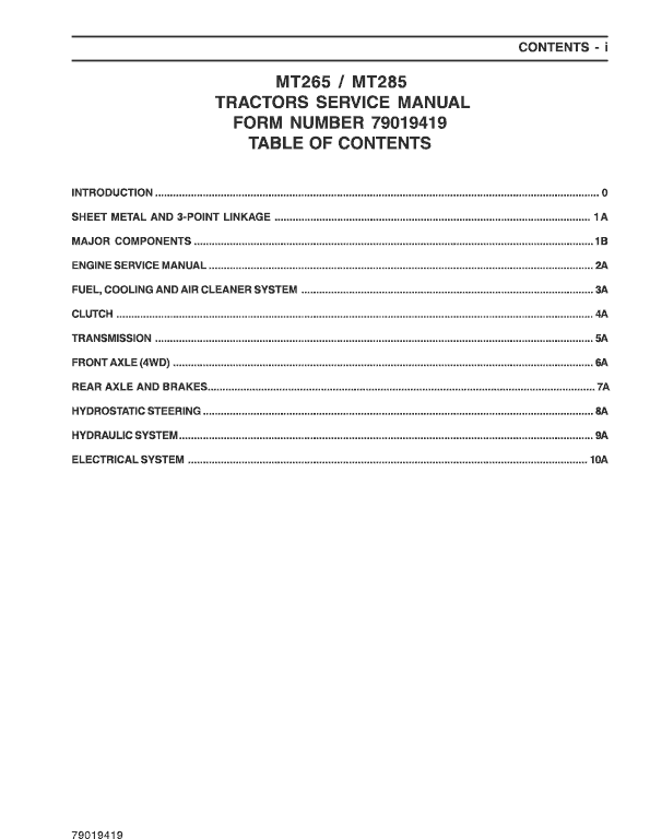
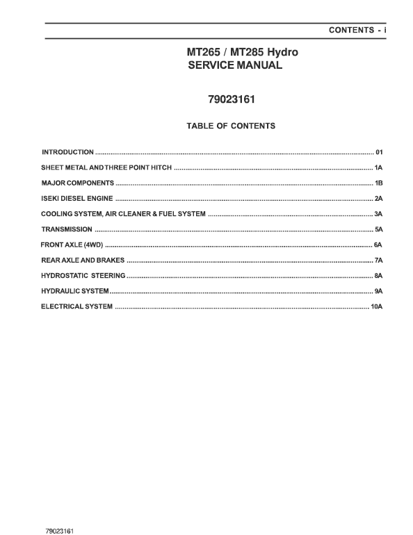
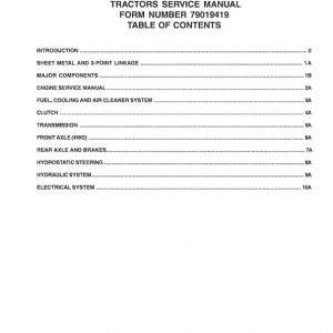
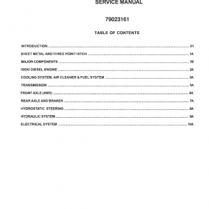
Challenger MT265, MT285 Manual TABLE OF CONTENTS
Introduction ………………………………………………………………………………………………………………………… 01
Sheet Metal And Three Point Hitch ………………………………………………………………………………………….1a
Major Components ……………………………………………………………………………………………………………….. 1b
Iseki Diesel Engine …………………………………………………………………………………………………………………2a
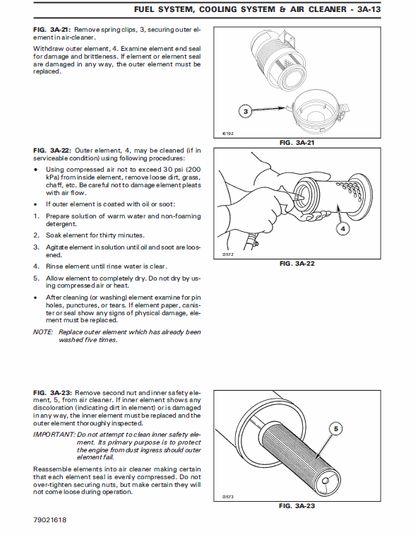
Cooling System, Air Cleaner & Fuel System ……………………………………………………………………………… 3a
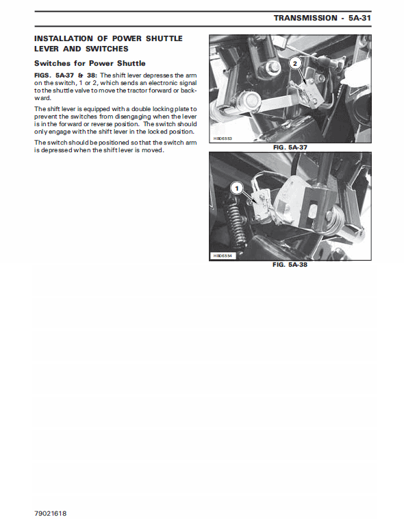
Transmission ………………………………………………………………………………………………………………………… 5a
Front Axle (4wd) …………………………………………………………………………………………………………………… 6a
Rear Axle And Brakes ……………………………………………………………………………………………………………. 7a
Hydrostatic Steering ……………………………………………………………………………………………………………… 8a
Hydraulic System ………………………………………………………………………………………………………………….. 9a
Electrical System …………………………………………………………………………………………………………………… 10a
MT265, MT285 Manual Extract –
PTO Clutch
The PTO is driven thru a wet multi-disced, hydraulically operated clutch pack. For the PTO to work, the mechanical PTO lever on the LH side of the tractor must be engaged and the on/off switch on the console must be in the “ON” position. When the switch is in the “ON” position, the PTO valve is energized allowing oil pressure to clamp the discs in the PTO clutch pack together and turn the PTO shaft.
Oil Supply to PTO Clutch Pack
Oil is transfered from the main hydraulic pump to a reducing valve. The reducing valve acts as a flow divider, dividing the flow of oil to a primary and secondary circuit.
Oil for the PTO clutch pack is supplied by the secondary circuit of the reducing valve. The reducing valve also maintains line pressure to the secondary circuit to operate the PTO clutch pack. Refer to the HYDRAULIC section for more information on the reducing valve.
Be the first to review “Challenger MT265, MT285 Tractor Service Manual”
You must be logged in to post a review.


Reviews
There are no reviews yet.