Case JX1075N, JX1095N Tractor Service Manual
$35.00
Manual Included:
• Service Manual: 976 pages
Specifications:
• Brand: Case
• Model: JX1075N, JX1095N
• Type: Tractor
• Manuals: Service Manual
• Publication Number: 87352295 (June 2005)
• Language: English
• Format: PDF
- Description
- Reviews (0)
Description
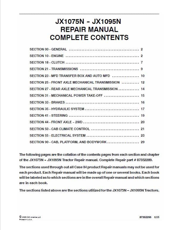
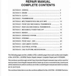
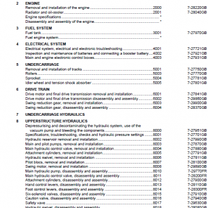
Table of Content (Service Manual)
SECTION 00 – GENERAL . . . . . . . . . . . . . . . . . . . . . . . . . . . . . . . . . . . . . . . . . . . . 2
SECTION 10 – ENGINE . . . . . . . . . . . . . . . . . . . . . . . . . . . . . . . . . . . . . . . . . . . . . . 2
SECTION 18 – CLUTCH . . . . . . . . . . . . . . . . . . . . . . . . . . . . . . . . . . . . . . . . . . . . . . 7
SECTION 21 – TRANSMISSIONS . . . . . . . . . . . . . . . . . . . . . . . . . . . . . . . . . . . . . 9
SECTION 23 – MFD TRANSFER BOX AND AUTO MFD . . . . . . . . . . . . . . . . . 10
SECTION 25 – FRONT AXLE MECHANICAL TRANSMISSION . . . . . . . . . . . 12
SECTION 27 – REAR AXLE MECHANICAL TRANSMISSION . . . . . . . . . . . . . 14
SECTION 31 – MECHANICAL POWER TAKE-OFF . . . . . . . . . . . . . . . . . . . . . . 15
SECTION 33 – BRAKES . . . . . . . . . . . . . . . . . . . . . . . . . . . . . . . . . . . . . . . . . . . . . . 16
SECTION 35 – HYDRAULIC SYSTEM . . . . . . . . . . . . . . . . . . . . . . . . . . . . . . . . . . 17
SECTION 41 – STEERING . . . . . . . . . . . . . . . . . . . . . . . . . . . . . . . . . . . . . . . . . . . . 19
SECTION 44 – FRONT AXLE — 2WD . . . . . . . . . . . . . . . . . . . . . . . . . . . . . . . . . . . 20
SECTION 50 – CAB CLIMATE CONTROL . . . . . . . . . . . . . . . . . . . . . . . . . . . . . . 21
SECTION 55 – ELECTRICAL SYSTEM . . . . . . . . . . . . . . . . . . . . . . . . . . . . . . . . . 23
SECTION 90 – CAB, PLATFORM, AND BODYWORK . . . . . . . . . . . . . . . . . . . . 29
The following pages are the collation of the contents pages from each section and chapter of the JX1075N — JX1095N Tractor Repair manual. Complete Repair Manual# 87352289.
Manual Extract: Lock-Time the Fuel Injection Pump with Pump Removed from the Tractor
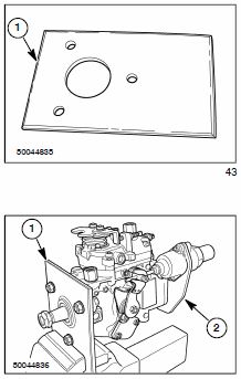
Use a metal piece of 1/4 inch flat stock 5 inches wide by 8 inches long.
2. Drill a 2 inch diameter hole in the flat stock 2.5 inches in from one end and 2.5 inches in from the side.
3. Insert the front (shaft end) of the injection pump into the 2 inch hole of the flat plate. Using the pump mounting holes as a template place three marks on the flat plate.
4. Drill three 3/8 inch diameter holes in the flat plate.
5. Clamp the mounting plate (1) in a vise. Secure the injection pump (2) to the mounting plate using three 5/16 inch x 1 inch bolts and nuts.
6. Place the woodruff key on a hard surface of the workbench. Using a chisel, drive a small mark into both sides of the key. This will assure the key fits tightly onto the pump driveshaft and prevent the key from sliding out of the pump driveshaft when installing the pump into the engine.
7. Install the woodruff key into the slot in the pump driveshaft making sure that it is correctly positioned and fits tightly.
Be the first to review “Case JX1075N, JX1095N Tractor Service Manual”
You must be logged in to post a review.


Reviews
There are no reviews yet.