Case DX21, DX24 Tractor Service Manual
$34.00
Manual Included:
• Service Manual: 720 pages
Specifications:
• Brand: Case
• Model: DX21, DX24
• Type: Tractor
• Manuals: Service Manual
• Publication Number: 87055743 (Nov 2004)
• Language: English
• Format: PDF
- Description
- Reviews (0)
Description
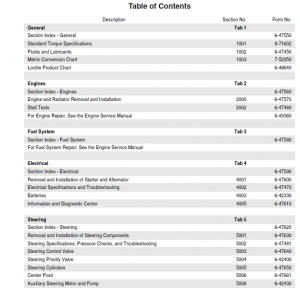
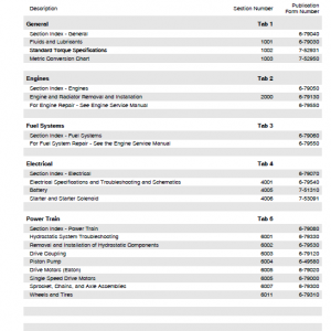
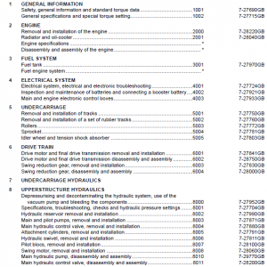
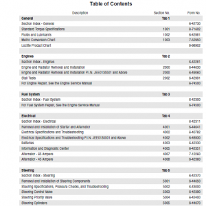
Table of Contents
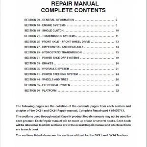
SECTION 00 – GENERAL INFORMATION . . . . . . . . . . . . . . . . . . . . . . . . . . . . . . 2
SECTION 10 – ENGINE SYSTEMS . . . . . . . . . . . . . . . . . . . . . . . . . . . . . . . . . . . . 3
SECTION 18 – SINGLE CLUTCH . . . . . . . . . . . . . . . . . . . . . . . . . . . . . . . . . . . . . . 10
SECTION 21 – TRANSMISSION SYSTEMS . . . . . . . . . . . . . . . . . . . . . . . . . . . . . 11
SECTION 25 – FRONT AXLE — FRONT WHEEL DRIVE . . . . . . . . . . . . . . . . . . 13
SECTION 27 – DIFFERENTIAL AND REAR AXLE . . . . . . . . . . . . . . . . . . . . . . . 14
SECTION 29 – HYDROSTATIC TRANSMISSION . . . . . . . . . . . . . . . . . . . . . . . . 15
SECTION 31 – POWER TAKE-OFF SYSTEMS . . . . . . . . . . . . . . . . . . . . . . . . . . 19
SECTION 33 – BRAKES . . . . . . . . . . . . . . . . . . . . . . . . . . . . . . . . . . . . . . . . . . . . . . 20
SECTION 35 – HYDRAULIC SYSTEM . . . . . . . . . . . . . . . . . . . . . . . . . . . . . . . . . . 21
SECTION 41 – POWER STEERING SYSTEM . . . . . . . . . . . . . . . . . . . . . . . . . . . 24
SECTION 44 – WHEELS AND TIRES . . . . . . . . . . . . . . . . . . . . . . . . . . . . . . . . . . 26
SECTION 55 – ELECTRICAL SYSTEM . . . . . . . . . . . . . . . . . . . . . . . . . . . . . . . . . 26
SECTION 90 – PLATFORM . . . . . . . . . . . . . . . . . . . . . . . . . . . . . . . . . . . . . . . . . . . 32
The following pages are the collation of the contents pages from each section and chapter of the DX21 and DX24 Repair manual. Complete Repair Manual# 87055743.
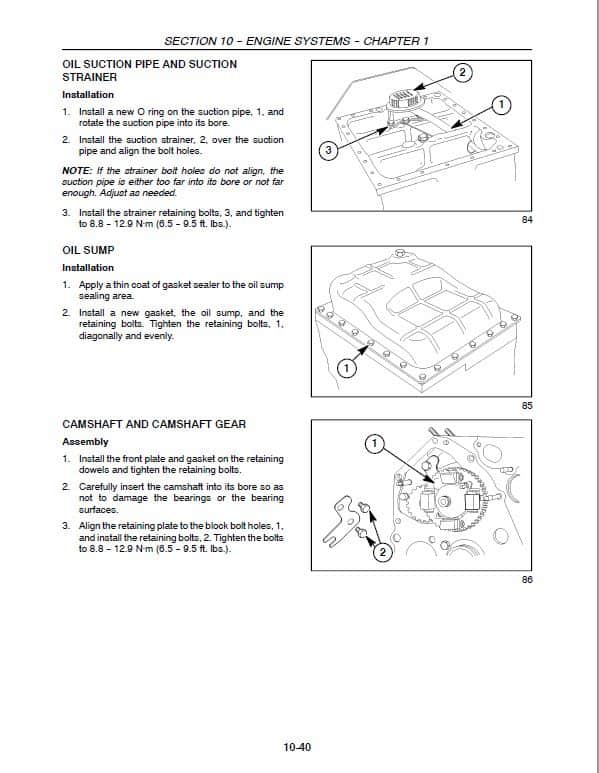
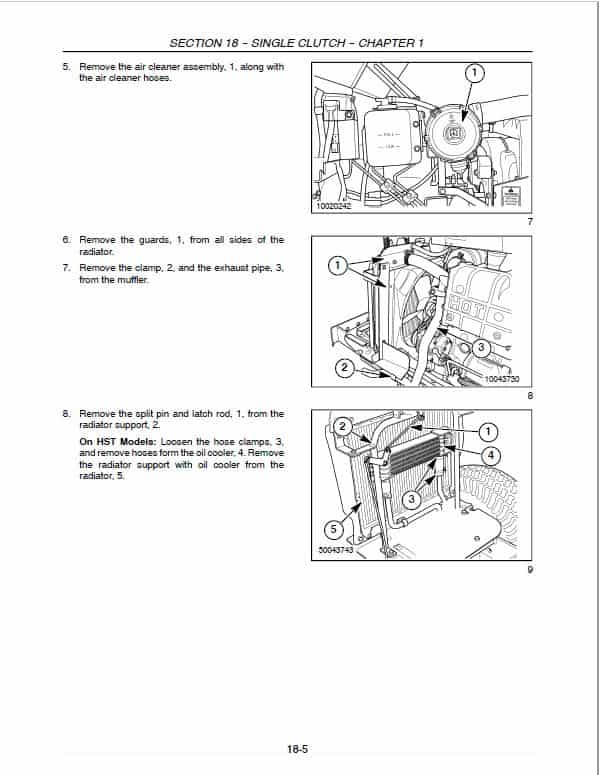
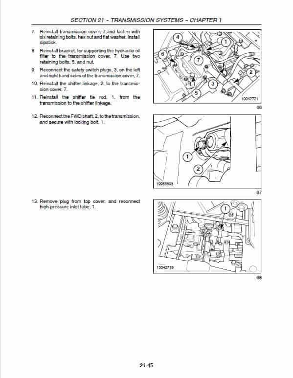
Manual Extract: Installation and Adjustment
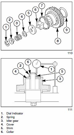
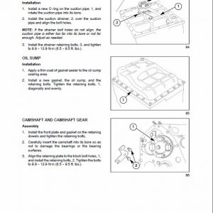
2. Install the thrust washer, 9, and align the timing marks on the idler gear, crankshaft gear, and camshaft gear, as shown in Figure 86, and install the idler gear on the port shaft.
3. Install the rotor, 6.
4. Install the oil pump cover, 5, shim, 4, spring, 3, and collar, 2. Secure the assembly to the shaft with retaining ring, 1
5. Using a dial indicator, 1, Measure the axial movement of the collar, 6. The standard clearance is 0.1 — 0.15mm(0.004 — 0.006 in.) and the maximum allowable is 0.20 mm (0.008 in.).
Install or remove shims, 5, as needed to obtain the standard clearance.
NOTE: Shims are available in 0.1 mm (0.004 in.), 0.15 mm (0.006 in.), 0.2 mm (0.008 in.), and 0.5 mm (0.020 in.) thickness.
IMPORTANT: Insufficient rotor clearance may cause binding and damage to the inner rotor cover or port block. Excessive clearance may allow the oil to bypass around the sides of the rotor resulting in loss of pressure and volume in the lubrication circuit.
6. Install the water pump and cooling fan. See Water Pump and Thermostat Installation and Cooling Fan Installation discussed later in this section.
7. Install the timing gear cover. See Timing Gear Cover Installation discussed earlier in this section.
8. Refill the radiator to its proper coolant level.
9. Replace the engine oil filter and fill the sump with oil.
Be the first to review “Case DX21, DX24 Tractor Service Manual”
You must be logged in to post a review.


Reviews
There are no reviews yet.