

Case D35, D40, D45 Tractor Service Manual
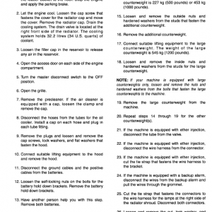
$35.00
Manual Included:
• Service Manual: 1400 pages
Specifications:
• Brand: Case
• Model: D35, D40, D45
• Type: Tractor
• Manuals: Service Manual
• Publication Number: 87622995 (Dec 2006)
• Language: English
• Format: PDF
- Description
- Reviews (0)
Description
Table of Contents
SECTION 00 – GENERAL INFORMATION . . . . . . . . . . . . . . . . . . . . . . . . . . . . . . 2
SECTION 10 – ENGINE . . . . . . . . . . . . . . . . . . . . . . . . . . . . . . . . . . . . . . . . . . . . . . 3
SECTION 18 – CLUTCH . . . . . . . . . . . . . . . . . . . . . . . . . . . . . . . . . . . . . . . . . . . . . . 10
SECTION 21 – TRANSMISSION . . . . . . . . . . . . . . . . . . . . . . . . . . . . . . . . . . . . . . . 11
SECTION 23 – DRIVELINE . . . . . . . . . . . . . . . . . . . . . . . . . . . . . . . . . . . . . . . . . . . 14
SECTION 25 – FWD FRONT AXLE . . . . . . . . . . . . . . . . . . . . . . . . . . . . . . . . . . . . 15
SECTION 27 – DIFFERENTIAL, REAR AXLE . . . . . . . . . . . . . . . . . . . . . . . . . . . 16
SECTION 29 – HYDROSTATIC TRANSMISSION . . . . . . . . . . . . . . . . . . . . . . . . 17
SECTION 31 – POWER TAKE-OFF (PTO) SYSTEMS . . . . . . . . . . . . . . . . . . . . 21
SECTION 33 – BRAKES . . . . . . . . . . . . . . . . . . . . . . . . . . . . . . . . . . . . . . . . . . . . . . 24
SECTION 35 – HYDRAULIC SYSTEM . . . . . . . . . . . . . . . . . . . . . . . . . . . . . . . . . . 24
SECTION 41 – STEERING . . . . . . . . . . . . . . . . . . . . . . . . . . . . . . . . . . . . . . . . . . . . 28
SECTION 44 – 2WD FRONT AXLE . . . . . . . . . . . . . . . . . . . . . . . . . . . . . . . . . . . . 29
SECTION 50 – CLIMATE CONTROL . . . . . . . . . . . . . . . . . . . . . . . . . . . . . . . . . . . 30
SECTION 55 – ELECTRICAL SYSTEM . . . . . . . . . . . . . . . . . . . . . . . . . . . . . . . . . 34
SECTION 90 – PLATFORM . . . . . . . . . . . . . . . . . . . . . . . . . . . . . . . . . . . . . . . . . . . 51
The following pages are the collation of the contents pages from each section and chapter of the D35, D40, D45 Repair manual. Complete Repair Manual# 87622993.
Manual Extract: ELECTRONIC LIFT CALIBRATION
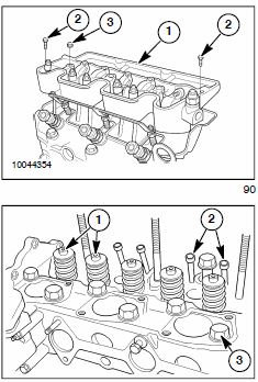 ROCKER ARM SHAFT AND SUPPORT BRACKET
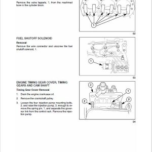
Removal
1. Remove the bolts, 2, and nuts, 3.
2. Remove the rocker arm shaft and support bracket as an assembly, 1.
NOTE: Alternately loosen the rocker support bolts a turn at a time to prevent distorting the rocker shaft.
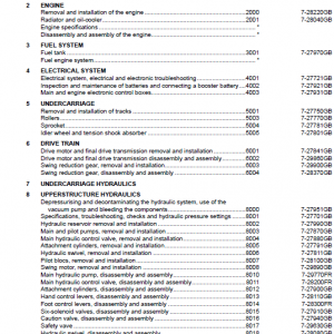
CYLINDER HEAD
Removal
1. Remove the valve stem caps, 1, and push rods, 2.
NOTE: Keep all valve components in separately marked containers for re-assembly in their original location.
2. To remove the cylinder head, remove the cylinder head bolts, 3, by alternately loosening a half turn at a time to prevent warping the head.
Be the first to review “Case D35, D40, D45 Tractor Service Manual”
You must be logged in to post a review.
Reviews
There are no reviews yet.