Case 521G Loader Service Manual
$37.00
Manual Included:
• Service Manual: 2829 pages & 2831 pages (Tier 4B) and 2087 pages (Tier 2)
Specifications:
• Brand: Case
• Model: 521G
• Type: Loader
• Manuals: Service Manual
• Publication Numbers: 51428262 (Dec 2017), 48083739 (Jul 2018) and 51428203 (Nov 2017)
• Language: English
• Format: PDF
- Description
- Reviews (0)
Description
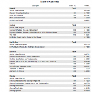
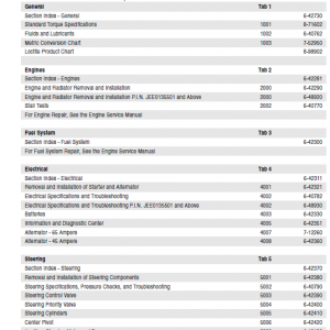
Table of Contents
- Content
- Introduction
- Engine
- Transmission
- Four Wheel Drive System
- Front Axle
- Rear Axle
- Brakes and Controls
- Hydraulic System
- Frames and ballasting
- Steering
- Wheels
- Cab climate control
- Electrical System
- Front Loader and Bucket
- Platform, Cab, Bodywork and Decals
- Special Tool Index
- Electrical Schematics
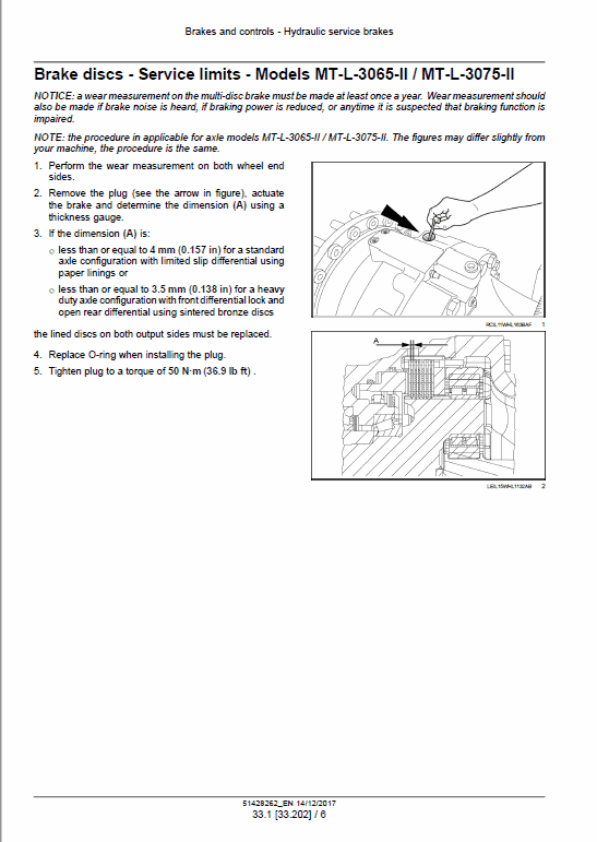
Manual Extract: Hydraulic service brakes – Bleed – Bleeding the Brake System
1. Check the level of the hydraulic fluid in the reservoir.
Add fluid to the reservoir if necessary.
NOTE: if the machine is equipped with quick-attached components, disconnect them from machine prior to proceeding.
2. Raise the loader arms and install the safety link.
3. Put the articulation lock in the LOCKED position.
4. Apply the parking brake.
5. To prime the pump, do the following:
A. Turn the ignition switch to the OFF position.
B. Turn the timed disconnect switch to the OFF position.
6. Disconnect the connectors from the ECU to prevent the start of the engine.
7. Loosen the fitting on the brake pump section hose 9. Turn the ignition switch to ON and crank the engine (the engine will not start).
10. Do the following:
A. Turn the ignition switch to ON. and crank the engine (the engine will not start).
B. Crank the engine (the engine will not start) until a few drops of oil leak past the fitting.
C. After a few drops of oil are noticed, tighten the fitting.
11. Turn the timed disconnect switch to the OFF position.
12. Connect the connectors on the ECU.
13. Turn the timed disconnect switch to the ON position.
14. Start the engine. Idle until both brake accumulators are fully charged.
NOTE: after approximately 30 s the low brake pressure indicator light will not be illuminated.
15. Turn the ignition switch to the OFF position.
16. Push the brake pedal to relieve the hydraulic pressure in the brake system (approximately 20 times).
17. Remove the plastic and rubber cap from each wheel.
Slowly open the bleed screws.
18. Attach a hose to the bleed screws to prevent spillage.
Submerge the hoses in fluid to prevent that air enters to the brake system.
19. Turn the ignition switch to the ON position. Start the engine and run at low idle for few minutes.
20. Depress the brake pedal until the flow is clear with no air bubbles present in both tubes.
21. Close all four wheel end bleed screws.
22. Replace all of the caps and plugs on the wheel end.
23. Check and verify that the hydraulic fluid level is filled to specification. Fill as required.
Be the first to review “Case 521G Loader Service Manual”
You must be logged in to post a review.


Reviews
There are no reviews yet.