Case 430, 530 Construction King Loader Service Manual
$33.00
Manual Included:
- Service Manual: 422 Pages & 610 Pages
Specifications:
- Brand: New Holland
- Model: Case 430 and 530
- Type: Construction King Loader
- Manuals: Service Manual
- Publication Numbers: 9-70011
- Language: English
- Format: PDF
- Description
- Reviews (0)
Description
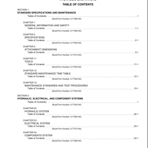
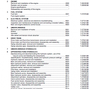
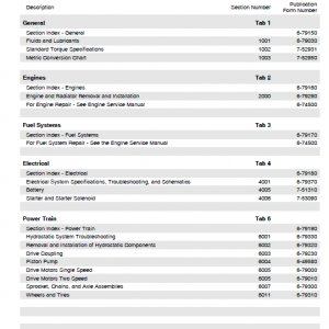
Table of Content
- General
- Engines
- Fuel System
- Electrical
- Steering
- Power Train
- Brakes
- Hydraulics
- Chassis
MANUAL EXTRACT: MAIN RELIEF VALVE
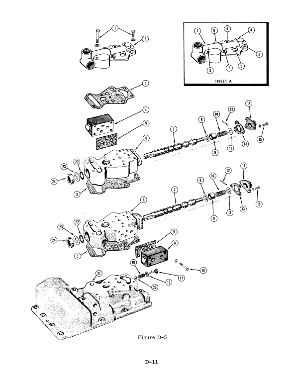
When a cylinder bottoms or is held by a load, the main relief opens to protect hydraulic system components. When the main relief valve opens, the oil can go directly to the sump through a passage in the valve rather than to the cylinder.
The main relief is a pilot operated relief valve.
This means that a pilot plunger controls the opening of the relief valve to give a more gradual operation of the relief valve.
The main relief valve is located in the valve inlet. Due to a small hole in the relief valve poppet, the same pressure is maintained above and below the poppet and the poppet remains seated until approximately 2000 P. S. I . pressure is reached.
Then the pilot plunger is pushed off its seat and the pressure above the poppet falls off more rapidly than the pressure below it. Because of this pressure differential, the poppet is forced off its seat and the oil returns to sump instead of going to a cylinder.
SECONDARY RELIEF VALVES
Under certain conditions, when digging or lifting with the dump cylinder spool in neutral, extremely high pressures are built up in the dump cylinders due to the dump cylinder piston rod being forced against a solid column of oil . Two secondary relief valves located in the control valve between the dump cylinder spool and the port of the valve leading to the cylinders protect the dump cylinders.
When a load in excess of the secondary relief valve setting is placed on the dump cylinders, the secondary relief valve spring compresses and allows oil to bleed off to sump reducing the pressure in the cylinders
LOAD CHECK VALVE
As a spool is actuated slightly, “feathered”, the load may tend to force oil out of the applied end of the cylinders if the pressure supplied by the pump is not as great as that created by the load. Each spool has a load check valve to hold the load. The load check valve prevents the oil from the applied end of the cylinder from flowing back through the valve, but allows the oil to flow to the cylinder, see Figure 43. Load check valves also hold the load if the engine stalls while a spool is actuated.
Be the first to review “Case 430, 530 Construction King Loader Service Manual”
You must be logged in to post a review.


Reviews
There are no reviews yet.