Case 2120, 2130, 2140, 2150 Tractor Service Manual
$34.00
Manual Included:
• Service Manual: 598 pages
Specifications:
• Brand: New Holland
• Model: 2120, 2130, 2140, 2150
• Type: Tractor
• Manuals: Service Manual
• Publication Numbers: 7-35081 (April 1991)
• Language: English
• Format: PDF
- Description
- Reviews (0)
Description
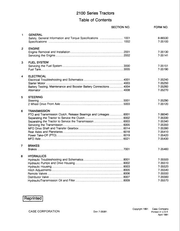
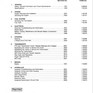
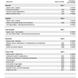
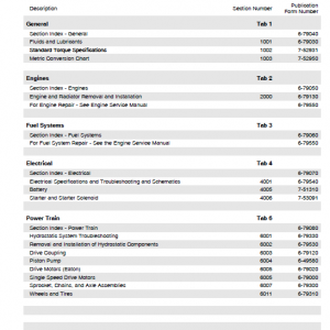
Table of Content (Service Manual)
- General
- Engine
- Fuel System
- Electrical
- Steering
- Transmission
- Brakes
- Hydraulics
- Chassis and Mounted Equipment
Manual Extract: Fuel Injection Pump Installation and Timing
The Fuel Injection Pump must be timed whenever
A. A new pump is installed.
B. A repaired pump is installed.
NOTE: When installing new or repaired Fuel Injection Pumps they must all be of the same class.
Position No. 1 piston at TDC on the compression stroke (both valves closed). Remove the rocker cover, rocker assembly and valve spring from the inlet valve and allow the valve to sit on top of the piston. Put a loaded dial gauge, OEM 1029, onto the top of the inlet valve stem and set to zero. Turn the crankshaft COUNTERCLOCKWISE until the piston has moved 3mm. Now turn the crankshaft CLOCKWISE until the dial gauge reads 2.92 mm. This will now have removed any backlash and will have set the injection timing to 16° B.T.D.C.
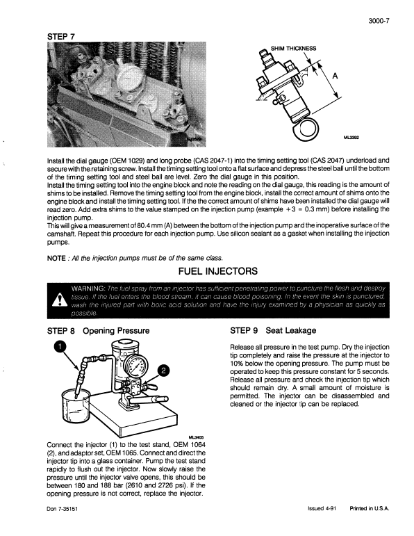
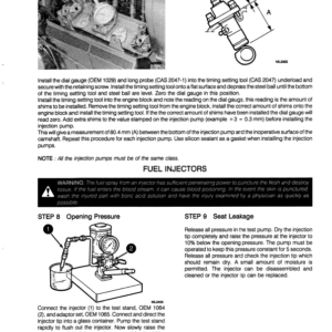
Install the dial gauge (OEM 1029) and long probe (CAS 204 7-1) into the timing setting tool (CAS 204 7) underload and secure with the retaining screw. Install the timing setting tool onto a flat surface and depress the steel ball until the bottom of the timing setting tool and steel ball are level. Zero the dial gauge in this position.
Install the timing setting tool into the engine block and note the reading on the dial gauge, this reading is the amount of shims to be installed. Remove the timing setting tool from the engine block, install the correct amount of shims onto the engine block and install the timing setting tool. If the the correct amount of shims have been installed the dial gauge will read zero.
Add extra shims to the value stamped on the injection pump (example + 3 = 0.3 mm) before installing the injection pump.
This will give a measurement of 80.4 mm (A) between the bottom of the injection pump and the inoperative surface of the camshaft. Repeat this procedure for each injection pump. Use silicon sealant as a gasket when installing the injection pumps.
NOTE : All the injection pumps must be of the same class.
Be the first to review “Case 2120, 2130, 2140, 2150 Tractor Service Manual”
You must be logged in to post a review.







Reviews
There are no reviews yet.