Sumitomo SH75X-3B Hydraulic Excavator Repair Service Manual
$40.00
Sumitomo Excavator SH75X-3B
Format: PDF
Manual Identification: WLSM0753B-00W, WDL0754-0T and WLST0753B-00W
English
- Sumitomo SH75X-3B Hydraulic Excavator Repair Service Manual – 448 Pages & 216 Pages
- Operators Manual – 190 Pages
- Description
- Reviews (0)
Description
Sumitomo SH75X-3B Hydraulic Excavator Repair Service Manual
Sumitomo Excavator SH75X-3B
Format: PDF
Manual Identification: WLSM0753B-00W, WDL0754-0T and WLST0753B-00W
English
- Sumitomo SH75X-3B Hydraulic Excavator Repair Service Manual – 448 Pages & 216 Pages
- Operators Manual – 190 Pages
Sumitomo SH75X-3B Manual TABLE OF CONTENTS
Introduction
Using Technical Information
Precautions for Use
Tightening Torque
Specifications
Performances
Hydraulic Pump
Assembly and Disassembly Procedures …………………………………………………………..1
1. Tools and Jigs………………………………………………………………………………………1
2. Cautions ……………………………………………………………………………………………..1
3. Disassembly Procedures……………………………………………………………………….2
4. Assembly Procedures……………………………………………………………………………8
5. Disassembly of Gear Pump………………………………………………………………….14
6. Assembly of Gear Pump………………………………………………………………………17
Internal structure diagram……………………………………………………………………………..23
Travel Unit
Maintenance Procedures………………………………………………………………………………28
1. Tools …………………………………………………………………………………………………28
2. Tightening Torque……………………………………………………………………………….32
3. Weight Table………………………………………………………………………………………32
Disassembly ……………………………………………………………………………………………….33
1. Preparations ………………………………………………………………………………………33
2. General Work Precautions …………………………………………………………………..33
3. Disassembly Procedure……………………………………………………………………….34
Maintenance Standards………………………………………………………………………………..52
1. Seals ………………………………………………………………………………………………..52
2. Maintenance Standards for Worn Parts …………………………………………………52
Assembly ……………………………………………………………………………………………………54
1. Preparations ………………………………………………………………………………………54
2. General Work Precautions …………………………………………………………………..54
3. Assembly Procedures………………………………………………………………………….54
Performance Confirmation Test ……………………………………………………………………..72
3-Dimensional Disassembly Diagram of Reduction Gear Section……………………….73
3-Dimensional Disassembly Diagram of Hydraulic Motor Section……………………….74
Travel Motor ………………………………………………………………………………………………..75
Swing Unit
Maintenance Procedures………………………………………………………………………………77
1. Trouble and Countermeasures ……………………………………………………………..77
2. Tool …………………………………………………………………………………………………..84
3. Disassembly Procedures……………………………………………………………………..87
4. Assembly Procedures………………………………………………………………………….97
5. Quality Check after Assembly …………………………………………………………….108
6. Maintenance Standards …………………………………………………………………….109
7. Development Diagram……………………………………………………………………….112
8. Configuration Diagram……………………………………………………………………….114
Reverse Prevention Valve……………………………………………………………………………117
1. Trouble and Countermeasures ……………………………………………………………117
2. Tools for Assembly and Disassembly …………………………………………………..118
Reverse Prevention Valve Breakdown Diagram ……………………………………………..122
Control Valve
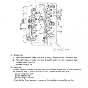
Disassembly ……………………………………………………………………………………………..123
1. Cautions for Disassembly…………………………………………………………………..123
2. Disassembly Procedures……………………………………………………………………123
Cleaning …………………………………………………………………………………………………..127
Inspection …………………………………………………………………………………………………127
Assembly ………………………………………………………………………………………………….128
1. Sub Assembly…………………………………………………………………………………..128
2. Assembly of Control Valve Main Unit …………………………………………………..129
Relief Valve……………………………………………………………………………………………….133
1. Procedures for Assembly and Disassembly of Main Relief Valve …………….133
2. Procedures for Assembly and Disassembly of Overload Relief Valve……….134
3. Relief Valve Adjustment……………………………………………………………………..135
Installation ………………………………………………………………………………………………..136
Operation………………………………………………………………………………………………….136
Control Valve Specifications List…………………………………………………………………..136
Troubles and Countermeasures …………………………………………………………………..137
Control Valves Overall…………………………………………………………………………….137
Relief Valve …………………………………………………………………………………………..138
Hydraulic System Overall………………………………………………………………………..138
Part List ……………………………………………………………………………………………………139
Reference Diagram…………………………………………………………………………………….140
Cylinder
Structural Diagram……………………………………………………………………………………..152
1. Boom Cylinder (mono-boom machine)…………………………………………………152
2. Boom Cylinder (offset-boom machine)…………………………………………………153
3. Arm Cylinder (mono-boom machine) …………………………………………………..154
4. Arm Cylinder (offset-boom machine)……………………………………………………155
5. Bucket Cylinder (mono-boom machine) ……………………………………………….156
6. Bucket Cylinder (offset-boom machine) ……………………………………………….157
7. Offset Cylinder (offset-boom machine)…………………………………………………158
8. Blade Cylinder (mono-boom/offset-boom machine)……………………………….159
Maintenance Procedures…………………………………………………………………………….160
1. Explanation of Functions ……………………………………………………………………160
2. Maintenance inspection and service ……………………………………………………163
3. Trouble diagnostics……………………………………………………………………………164
4. Storage standards …………………………………………………………………………….169
5. Assembly and disassembly procedures ……………………………………………….170
Specialty Tool and Jig for Repair ………………………………………………………………….186
1. Tool Dimensions ……………………………………………………………………………….186
2. Handling of Specialty Jigs for Cylinder Repair ………………………………………187
Remote Control Valve
Safety Items………………………………………………………………………………………………208
1. Cautions Concerning Operator’s Manual ……………………………………………..208
2. Safety Cautions ………………………………………………………………………………..208
3. Disclaimer………………………………………………………………………………………..209
For Operation…………………………………………………………………………………………….210
1. Summary …………………………………………………………………………………………210
2. Specifications …………………………………………………………………………………..210
3. Structure………………………………………………………………………………………….210
4. Function…………………………………………………………………………………………..210
5. Operation…………………………………………………………………………………………211
6. Maintenance Procedures …………………………………………………………………..213
7. Causes of Trouble and Countermeasures…………………………………………….224
8. Remote Control Valve Assembly Cross-Section Diagram……………………….225
9. Special Jig Assembly Cross-Section Diagram and Detailed Diagram……….226
For Travel Use……………………………………………………………………………………………227
1. Structure………………………………………………………………………………………….227
2. Operation Explanation……………………………………………………………………….228
3. Assembly and Disassembly………………………………………………………………..231
4. Troubles and Countermeasures ………………………………………………………….234
For Offset and Blade…………………………………………………………………………………..235
1. Operation Explanation……………………………………………………………………….235
2. Parts Maintenance and Replacement ………………………………………………….235
3. Causes of Trouble and Solutions…………………………………………………………236
4. Assembly and Disassembly Procedures ………………………………………………236
5. Structural Diagram…………………………………………………………………………….238
Solenoid Valve (3 stack)
Assembly Diagram……………………………………………………………………………………..239
Operation Principle …………………………………………………………………………………….239
Maintenance ……………………………………………………………………………………………..240
1. Assembly and Disassembly Precautions………………………………………………240
2. Assembly and Disassembly of Electromagnetic Switchover Valve……………240
3. Maintenance Standards …………………………………………………………………….241
4. Troubleshooting ………………………………………………………………………………..241
Cautions for Safety…………………………………………………………………………………242
Cushion Valve
Structure …………………………………………………………………………………………………..244
Operation Explanation ………………………………………………………………………………..245
Assembly and Disassembly…………………………………………………………………………247
General Precautions ………………………………………………………………………………247
Disassembly Procedure ………………………………………………………………………….247
Troubles and countermeasures ……………………………………………………………………248
The Sumitomo Manual Preface
The purpose of this Sumitomo Excavator manual is to assist dealers and repair serviceman in efficient repair and maintenance of their machinery. Carrying out the procedures as detailed, together with the use of any special tools needed.
Using the Sumitomo SH75X-3B Manual
To make information easier to find, there is an index at the beginning of each section listing the various parts in that section. At the beginning of each part there is a table of contents which should also be used as a guide to locate information.
To assist with locating information, each section of the manual is preceded by a contents page listing the repair operations, Each instruction within an operating has a sequence number. To complete the operation in the minimum time is possible follow the manual guideline and repair instructions.
When parts have to be replaced in either the SH75X-3B Hydraulic Excavator , it is essential that only genuine Sumitomo parts should be used. Special attention should be paid to the following points concerning repairs and the fitting of replacement parts and accessories.
Indexing
For convenience the manual is divided into section and parts, each page bearing a section and part number. The sections are subdivided into numbered operation. This simplifies cross referencing and enable the subject to be found easily.
Be the first to review “Sumitomo SH75X-3B Hydraulic Excavator Repair Service Manual”
You must be logged in to post a review.







Reviews
There are no reviews yet.