
Sumitomo SH235X-6 Hydraulic Excavator Repair Service Manual
$42.00
Sumitomo Excavator SH235X-6
Format: PDF
Manual Identification: WLSM2356-00T, WDL2356-1T
English
Jan. 2015
- Sumitomo SH235X-6 Hydraulic Excavator Repair Service Manual – 1370 Pages
- Operators Manual – 270 Pages
- Parts Catalog – 642 Pages
- Description
- Reviews (0)
Description
Sumitomo Excavator SH235X-6
Format: PDF
Manual Identification: WLSM2356-00T, WDL2356-1T
English
Jan. 2015
- Sumitomo SH235X-6 Hydraulic Excavator Repair Service Manual – 1370 Pages
- Operators Manual – 270 Pages
- Parts Catalog – 642 Pages
Sumitomo SH235X-6 Manual TABLE OF CONTENTS
Safety, general information and standard torque data…………………………………………… 4
General Information…………………………………………………………………………………………. 5
Standard Torque Data For Cap Screws And Nuts………………………………………………. 12
Specifications And Special Torque Settings………………………………………………………. 13
Abbreviation………………………………………………………………………………………………….. 14
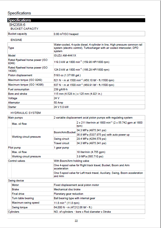
Specifications………………………………………………………………………………………………… 22
Main Equipment Table……………………………………………………………………………………. 32
Overall View………………………………………………………………………………………………….. 49
WORK RANGE DIAGRAM……………………………………………………………………………… 53
Main Unit Weight…………………………………………………………………………………………… 61
FLUIDS AND LUBRICANTS……………………………………………………………………………. 80
Circuits and Operation explanation…………………………………………………………………… 83
Main Equipment Structure and Operation Explanation………………………………………… 86
Hydraulic Pump…………………………………………………………………………………………….. 87
Travel Motor………………………………………………………………………………………………… 102
Swing Motor………………………………………………………………………………………………… 115
Control Valve………………………………………………………………………………………………. 121
5 Stack Solenoid Valve Operation Explanation………………………………………………… 156
Upper Pilot Valve (remote control valve)…………………………………………………………. 158
Travel Pilot Valve (remote control valve)…………………………………………………………. 163
Cushion Valve …………………………………………………………………………………………….. 168
3 Stack Proportional Valve (for pilot)………………………………………………………………. 174
Engine Summary…………………………………………………………………………………………. 178
Hydraulic Equipment Layout………………………………………………………………………….. 248
Overall view………………………………………………………………………………………………… 249
Port Diagram……………………………………………………………………………………………….. 254
Hydraulic Device………………………………………………………………………………………….. 279
Electrical and Engine Functions and Service Support……………………………………….. 280
Basic Functions…………………………………………………………………………………………… 281
Service Support…………………………………………………………………………………………… 356
Cautions for Maintenance……………………………………………………………………………… 397
Electrical Equipment Layout Diagram……………………………………………………………… 409
Connection Connector Pin Layout………………………………………………………………….. 439
Sequence Circuit Diagram…………………………………………………………………………….. 442
Removal / Installation and Assembly / Disassembly………………………………………… 457
Pressure Bleeding Operations……………………………………………………………………….. 464
Removal and Installation of Track………………………………………………………………….. 465
Removal and Installation of Shoe Assembly……………………………………………………. 466
Removal and Installation of Shoe Plate…………………………………………………………… 469
Removal and Installation of Roller………………………………………………………………….. 470
Removal and Installation of Upper Roller………………………………………………………… 471
Assembly and Disassembly of Upper Roller…………………………………………………….. 473
Assembly and Disassembly of Lower Roller…………………………………………………….. 482
Removal and Installation of Drive Sprocket……………………………………………………… 488
Removal and Installation of Take-up Roller……………………………………………………… 490
Assembly and Disassembly of Take-up Roller…………………………………………………. 492
Removal and Installation of Grease Cylinder…………………………………………………… 500
Assembly and Disassembly of Tension Shock Absorber…………………………………… 502
Removal and Installation of Center Joint…………………………………………………………. 505
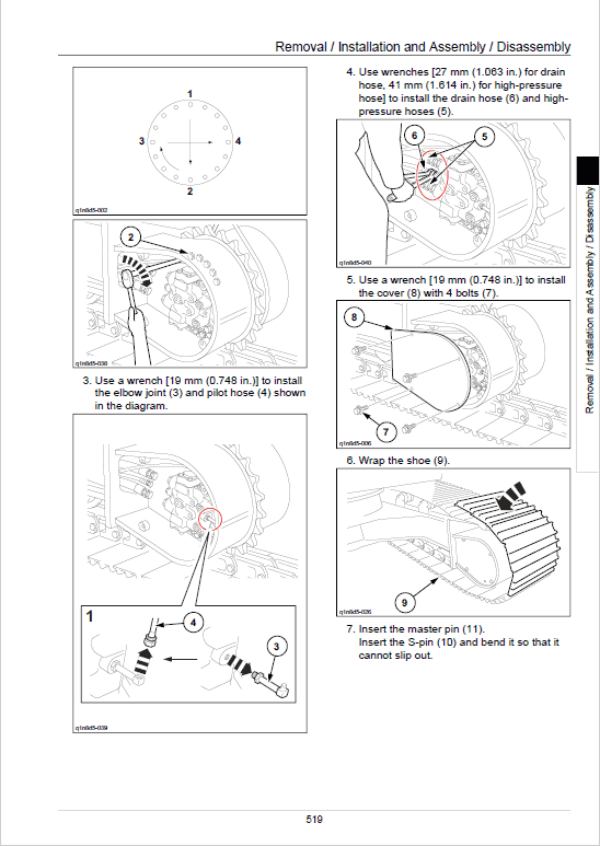
Assembly and Disassembly of Center Joint…………………………………………………….. 509
Removal and Installation of Travel Motor………………………………………………………… 516
Assembly and Disassembly of Travel Motor…………………………………………………….. 521
Removal and Installation of Swing Unit…………………………………………………………… 570
Assembly and Disassembly of Swing Motor…………………………………………………….. 574
Assembly and Disassembly of Swing Unit……………………………………………………….. 588
Removal and Installation of Hydraulic Pump……………………………………………………. 593
Procedures for Assembly and Disassembly of Hydraulic Pump Main Unit……………. 599
Pump Main Unit Maintenance Standards………………………………………………………… 604
Removal and Installation of Control Valve……………………………………………………….. 630
Procedures for Assembly and Disassembly of Control Valve……………………………… 635
Removal and Installation of Engine Assembly………………………………………………….. 657
Removal and Installation of Fuel Cooler, Engine Intercooler, Radiator, and Oil
Cooler………………………………………………………………………………………………………… 663
Removal and Installation of Turbo Charger……………………………………………………… 674
Removal and Installation of EGR Valve…………………………………………………………… 678
Removal and Installation of Top Cover……………………………………………………………. 682
Removal and Installation of Muffler………………………………………………………………… 683
Removal and Installation of Cylinder Head Cover…………………………………………….. 685
Removal and Installation of Cylinder Block……………………………………………………… 727
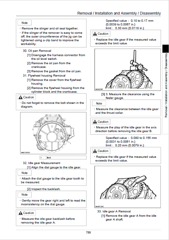
Lubrication System………………………………………………………………………………………. 777
Cooling System……………………………………………………………………………………………. 816
Removal and Installation of Exhaust Manifold………………………………………………….. 824
Disassembly, Removal and Installation of DPD Assembly…………………………………. 831
Removal and Installation of Fuel Supply Pump………………………………………………… 836
Removal and Installation of Common Rail Assembly………………………………………… 840
Removal and Installation of Injector………………………………………………………………… 847
Removal and Installation of Starter Motor……………………………………………………….. 856
Removal and Installation of Alternator…………………………………………………………….. 858
Preheating System………………………………………………………………………………………. 860
Removal and Installation of Fuel Tank……………………………………………………………. 872
Removal and Installation of Hydraulic Tank…………………………………………………….. 875
Removal and Installation of Pilot Blocs……………………………………………………………. 879
Removal and Installation of Travel Remote Control Valve…………………………………. 880
Procedures for Assembly and Disassembly of Travel Remote Control Valve……….. 883
Removal and Installation of Operation Remote Control Valve……………………………. 896
Procedures for Assembly and Disassembly of Operation Remote Control Valve….. 904
Removal and Installation of Blade Remote Control Valve………………………………….. 915
Assembly and Disassembly Procedures…………………………………………………………. 918
Removal and Installation of 5 Stack Solenoid………………………………………………….. 926
Removal and Installation of Cushion Valve……………………………………………………… 930
Assembly and Disassembly of Cushion Valve………………………………………………….. 933
Removal and Installation of Operator’s Seat……………………………………………………. 937
Removal and Installation of Cab Assembly……………………………………………………… 938
Removal and Installation of Wiper………………………………………………………………….. 942
Removal and Installation of Wiper Controller…………………………………………………… 943
Removal and Installation of Wiper Motor…………………………………………………………. 944
Removal and Installation of ECM…………………………………………………………………… 946
Removal and Installation of Computer A…………………………………………………………. 947
Removal and Installation of Computer B…………………………………………………………. 948
Removal and Installation of Monitor……………………………………………………………….. 949
Removal and Installation of Cab Front Glass…………………………………………………… 951
Window Lock Adjustment Procedures…………………………………………………………….. 953
Tightening torque…………………………………………………………………………………………. 955
Removal and Installation of Counterweight……………………………………………………… 956
Removal and Installation of Bucket………………………………………………………………… 960
Removal and Installation of Bucket Link………………………………………………………….. 962
Removal and Installation of Arm…………………………………………………………………….. 964
Removal and Installation of Boom………………………………………………………………….. 966
Removal and Installation of Blade………………………………………………………………….. 971
Removal and Installation of Bucket Cylinder……………………………………………………. 974
Removal and Installation of Arm Cylinder………………………………………………………… 977
Removal and Installation of Boom Cylinder……………………………………………………… 981
Removal and Installation of Blade Cylinder……………………………………………………… 986
Procedures for Operation/Assembly and Disassembly of Hydraulic Cylinder
(made by KYB)……………………………………………………………………………………………. 990
Removal and Installation of HBCV……………………………………………………………….. 1025
List of special tools…………………………………………………………………………………….. 1028
Maintenance standards and Measurement procedures………………………………….. 1051
Pressure Measurement and Adjustment Procedures………………………………………. 1052
Hydraulic Pump Flow Measurement Procedures……………………………………………. 1068
Drain Volume Measurement Procedures……………………………………………………….. 1072
Air Bleed Procedure……………………………………………………………………………………. 1075
Maintenance Standards………………………………………………………………………………. 1079
Bolt Size and Torque Table…………………………………………………………………………. 1095
New Machine Performance Judgment Table………………………………………………….. 1100
Air Conditioning…………………………………………………………………………………………… 1109
Air Conditioner Overall Diagram…………………………………………………………………… 1110
Assembly and Disassembly of Unit………………………………………………………………. 1152
Removal and Installation of Compressor……………………………………………………….. 1157
Removal and Installation of Condenser…………………………………………………………. 1158
Removal and Installation of Receiver Dryer…………………………………………………… 1160
Work Precautions………………………………………………………………………………………. 1162
Troubleshooting…………………………………………………………………………………………… 1173
Engine-side Diagnostic Trouble Code List……………………………………………………… 1177
Main Unit-side Diagnostic Trouble Code List………………………………………………….. 1179
Engine-side Trouble……………………………………………………………………………………. 1181
Main Unit-side Trouble………………………………………………………………………………… 1254
Symptom…………………………………………………………………………………………………… 1345
Data Reference Values……………………………………………………………………………….. 1359
The Sumitomo Manual Preface
The purpose of this Sumitomo Excavator manual is to assist dealers and repair serviceman in efficient repair and maintenance of their machinery. Carrying out the procedures as detailed, together with the use of any special tools needed.
Using the Sumitomo SH235X-6 Manual
To make information easier to find, there is an index at the beginning of each section listing the various parts in that section. At the beginning of each part there is a table of contents which should also be used as a guide to locate information.
To assist with locating information, each section of the manual is preceded by a contents page listing the repair operations, Each instruction within an operating has a sequence number. To complete the operation in the minimum time is possible follow the manual guideline and repair instructions.
When parts have to be replaced in either the SH235X-6 Hydraulic Excavator , it is essential that only genuine Sumitomo parts should be used. Special attention should be paid to the following points concerning repairs and the fitting of replacement parts and accessories.
Indexing
For convenience the manual is divided into section and parts, each page bearing a section and part number. The sections are subdivided into numbered operation. This simplifies cross referencing and enable the subject to be found easily.
Be the first to review “Sumitomo SH235X-6 Hydraulic Excavator Repair Service Manual”
You must be logged in to post a review.
Reviews
There are no reviews yet.