
Sumitomo SH145X-6 Hydraulic Excavator Repair Service Manual
$42.00
Sumitomo Excavator SH145X-6
Format: PDF
Manual Identification: WLSM1456-00T, WCL145X6-0T, WDL1356-1T
English
- Sumitomo SH145X-6 Hydraulic Excavator Repair Service Manual – 1358 Pages
- Operators Manual – 272 Pages
- Parts Catalog – 666 Pages
- Description
- Reviews (0)
Description
Sumitomo SH145X-6 Hydraulic Excavator Repair Service Manual
Sumitomo Excavator SH145X-6
Format: PDF
Manual Identification: WLSM1456-00T, WCL145X6-0T, WDL1356-1T
English
- Sumitomo SH145X-6 Hydraulic Excavator Repair Service Manual – 1358 Pages
- Operators Manual – 272 Pages
- Parts Catalog – 666 Pages
Sumitomo SH145X-6 Manual TABLE OF CONTENTS
Safety, general information and standard torque data…………………………………………… 4
General Information…………………………………………………………………………………………. 5
Standard Torque Data For Cap Screws And Nuts………………………………………………. 14
Specifications And Special Torque Settings………………………………………………………. 15
Abbreviation………………………………………………………………………………………………….. 16
Specifications………………………………………………………………………………………………… 24
Main Equipment Table……………………………………………………………………………………. 33
Overall View………………………………………………………………………………………………….. 51
Main Unit Weight…………………………………………………………………………………………… 57
FLUIDS AND LUBRICANTS……………………………………………………………………………. 75
Circuits and Operation explanation…………………………………………………………………… 79
Main Equipment Structure and Operation Explanation………………………………………… 82
Hydraulic Pump…………………………………………………………………………………………….. 83
Travel Motor………………………………………………………………………………………………… 100
Swing Motor………………………………………………………………………………………………… 113
Control Valve………………………………………………………………………………………………. 121
4 Stack Solenoid Valve Operation Explanation………………………………………………… 160
Upper Pilot Valve (remote control valve)…………………………………………………………. 162
Travel Pilot Valve (remote control valve)…………………………………………………………. 168
Blade Pilot Valve (remote control valve)………………………………………………………….. 173
Cushion Valve …………………………………………………………………………………………….. 175
Engine Summary…………………………………………………………………………………………. 180
Hydraulic Equipment Layout………………………………………………………………………….. 232
Overall View………………………………………………………………………………………………… 233
Port Diagram……………………………………………………………………………………………….. 239
Hydraulic Device………………………………………………………………………………………….. 264
Electrical and Engine Functions and Service Support……………………………………….. 265
Basic Functions…………………………………………………………………………………………… 266
Service Support…………………………………………………………………………………………… 339
Maintenance precautions………………………………………………………………………………. 384
Electrical Equipment Layout Diagram……………………………………………………………… 399
Connection Connector Pin Layout………………………………………………………………….. 429
Sequence Circuit Diagram…………………………………………………………………………….. 432
Removal / Installation and Assembly / Disassembly………………………………………… 449
Removal and Installation of Track………………………………………………………………….. 456
Removal and Installation of Shoe Assembly……………………………………………………. 457
Removal and Installation of Shoe Plate…………………………………………………………… 460
Removal and Installation of Roller………………………………………………………………….. 461
Removal and Installation of Upper Roller………………………………………………………… 462
Assembly and Disassembly of Upper Roller…………………………………………………….. 464
Removal and Installation of Lower Roller………………………………………………………… 470
Assembly and Disassembly of Lower Roller…………………………………………………….. 472
Removal and Installation of Drive Sprocket……………………………………………………… 478
Removal and Installation of Take-up Roller……………………………………………………… 480
Assembly and Disassembly of Take-up Roller…………………………………………………. 482
Removal and Installation of Grease Cylinder…………………………………………………… 490
Assembly and Disassembly of Tension Shock Absorber…………………………………… 492
Removal and Installation of Center Joint…………………………………………………………. 495
Assembly and Disassembly of Center Joint…………………………………………………….. 499
Removal and Installation of Travel Motor………………………………………………………… 506
Assembly and Disassembly of Travel Motor…………………………………………………….. 511
Removal and Installation of Swing Unit…………………………………………………………… 549
Assembly and Disassembly of Swing Motor…………………………………………………….. 553
Assembly and Disassembly of Swing Unit……………………………………………………….. 566
Removal and Installation of Hydraulic Pump……………………………………………………. 570
Removal and Installation of Pump Coupling…………………………………………………….. 574
Procedures for Assembly and Disassembly of Hydraulic Pump Main Unit……………. 577
Pump Main Unit Maintenance Standards………………………………………………………… 583
Removal and Installation of Control Valve……………………………………………………….. 607
Procedures for Assembly and Disassembly of Control Valve……………………………… 612
Removal and Installation of Engine Assembly………………………………………………….. 653
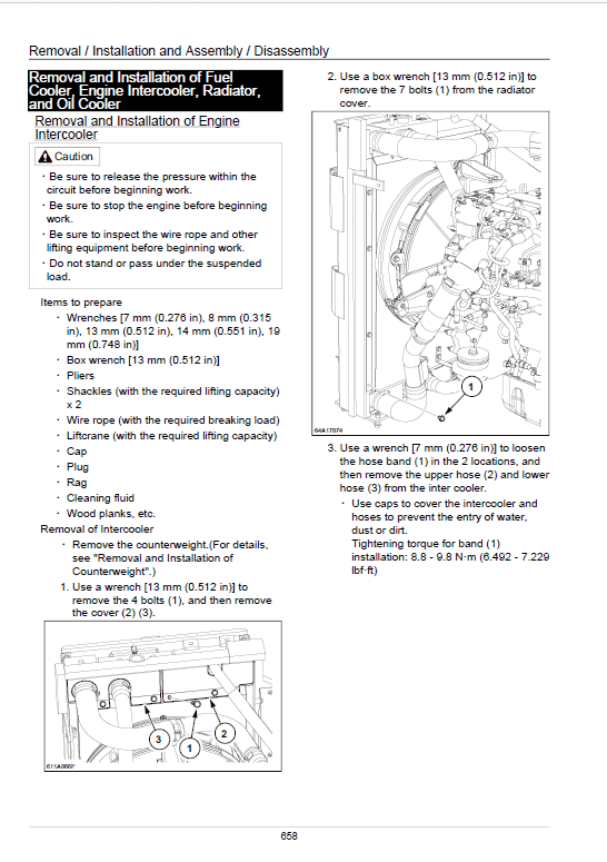
Removal and Installation of Fuel Cooler, Engine Intercooler, Radiator, and Oil
Cooler………………………………………………………………………………………………………… 658
Removal and Installation of Turbo Charger……………………………………………………… 667
Removal and Installation of EGR Valve…………………………………………………………… 670
Removal and Installation of EGR Cooler…………………………………………………………. 671
Removal and Installation of EGR Valve…………………………………………………………… 673
Removal and Installation of Top Cover……………………………………………………………. 674
Removal and Installation of Muffler………………………………………………………………… 675
Removal and Installation of Cylinder Head Cover…………………………………………….. 677
Removal and Installation of Cylinder Block……………………………………………………… 716
Lubrication System………………………………………………………………………………………. 767
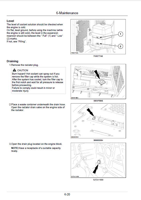
Cooling System……………………………………………………………………………………………. 818
Removal and Installation of Exhaust Manifold………………………………………………….. 824
Disassembly, Removal and Installation of DPD Assembly…………………………………. 829
Removal and Installation of Fuel Supply Pump………………………………………………… 834
Removal and Installation of Common Rail Assembly………………………………………… 848
Removal and Installation of Injector………………………………………………………………… 851
Removal and Installation of Starter Motor……………………………………………………….. 856
Removal and Installation of Alternator…………………………………………………………….. 857
Preheating System………………………………………………………………………………………. 858
Removal and Installation of Fuel Tank……………………………………………………………. 870
Removal and Installation of Hydraulic Oil Tank………………………………………………… 873
Removal and Installation of Pilot Blocs……………………………………………………………. 877
Removal and Installation of Travel Remote Control Valve…………………………………. 878
Procedures for Assembly and Disassembly of Travel Remote Control Valve……….. 881
Removal and Installation of Operation Remote Control Valve……………………………. 894
Procedures for Assembly and Disassembly of Operation Remote Control Valve….. 902
Removal and Installation of Blade Remote Control Valve………………………………….. 913
Assembly and Disassembly Procedures…………………………………………………………. 916
Removal and Installation of 4 Stack Solenoid………………………………………………….. 924
Removal and Installation of Cushion Valve……………………………………………………… 927
Assembly and Disassembly of Cushion Valve………………………………………………….. 931
Removal and Installation of Operator’s Seat……………………………………………………. 935
Removal and Installation of Cab Assembly……………………………………………………… 936
Removal and Installation of Wiper………………………………………………………………….. 940
Removal and Installation of Wiper Controller…………………………………………………… 941
Removal and Installation of Wiper Motor…………………………………………………………. 942
Removal and Installation of ECM…………………………………………………………………… 944
Removal and Installation of Computer A…………………………………………………………. 945
Removal and Installation of Computer B…………………………………………………………. 946
Removal and Installation of Monitor……………………………………………………………….. 947
Removal and Installation of Cab Front Glass…………………………………………………… 948
Window Lock Adjustment Procedures…………………………………………………………….. 950
Tightening torque…………………………………………………………………………………………. 952
Removal and Installation of Counterweight……………………………………………………… 953
Removal and Installation of Bucket………………………………………………………………… 957
Removal and Installation of Bucket Link………………………………………………………….. 959
Removal and Installation of Arm…………………………………………………………………….. 961
Removal and Installation of Boom………………………………………………………………….. 963
Removal and Installation of Blade………………………………………………………………….. 969
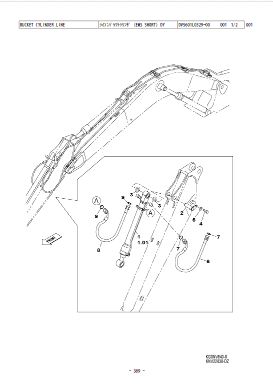
Removal and Installation of Bucket Cylinder……………………………………………………. 971
Removal and Installation of Arm Cylinder………………………………………………………… 974
Removal and Installation of Boom Cylinder……………………………………………………… 979
Removal and Installation of Blade Cylinder……………………………………………………… 984
Procedures for Operation/Assembly and Disassembly of Hydraulic Cylinder
(made by KYB)……………………………………………………………………………………………. 988
Removal and Installation of HBCV……………………………………………………………….. 1028
List of special tools…………………………………………………………………………………….. 1031
Maintenance standards and Measurement procedures………………………………….. 1053
Pressure Measurement and Adjustment Procedures………………………………………. 1054
Hydraulic Pump Flow Measurement Procedures……………………………………………. 1069
Drain Volume Measurement Procedures……………………………………………………….. 1073
Air Bleed Procedure……………………………………………………………………………………. 1076
Maintenance Standards………………………………………………………………………………. 1079
Bolt Size and Torque Table…………………………………………………………………………. 1094
Air Conditioning…………………………………………………………………………………………… 1101
Air Conditioner Overall Diagram…………………………………………………………………… 1102
Assembly and Disassembly of Unit………………………………………………………………. 1144
Removal and Installation of Compressor……………………………………………………….. 1149
Removal and Installation of Condenser…………………………………………………………. 1150
Removal and Installation of Receiver Dryer…………………………………………………… 1152
Work Precautions………………………………………………………………………………………. 1153
Troubleshooting…………………………………………………………………………………………… 1163
Engine-side Diagnostic Trouble Code List……………………………………………………… 1166
Main Unit-side Diagnostic Trouble Code List………………………………………………….. 1168
Engine-side Trouble……………………………………………………………………………………. 1170
Main Unit-side Trouble………………………………………………………………………………… 1238
Symptom…………………………………………………………………………………………………… 1335
Data Reference Values……………………………………………………………………………….. 1348
The Sumitomo Manual Preface
The purpose of this Sumitomo Excavator manual is to assist dealers and repair serviceman in efficient repair and maintenance of their machinery. Carrying out the procedures as detailed, together with the use of any special tools needed.
Using the Sumitomo SH145X-6 Manual
To make information easier to find, there is an index at the beginning of each section listing the various parts in that section. At the beginning of each part there is a table of contents which should also be used as a guide to locate information.
To assist with locating information, each section of the manual is preceded by a contents page listing the repair operations, Each instruction within an operating has a sequence number. To complete the operation in the minimum time is possible follow the manual guideline and repair instructions.
When parts have to be replaced in either the SH145X-6 Hydraulic Excavator , it is essential that only genuine Sumitomo parts should be used. Special attention should be paid to the following points concerning repairs and the fitting of replacement parts and accessories.
Indexing
For convenience the manual is divided into section and parts, each page bearing a section and part number. The sections are subdivided into numbered operation. This simplifies cross referencing and enable the subject to be found easily.
Be the first to review “Sumitomo SH145X-6 Hydraulic Excavator Repair Service Manual”
You must be logged in to post a review.
Reviews
There are no reviews yet.