
Sumitomo SH135X-3B Hydraulic Excavator Repair Service Manual
$44.00
Sumitomo Excavator SH135X-3B
Format: PDF
Manual Identification: WLST1353B-00W, WLST1305TS-01W, WLSM1353B-00W, WDL1254-0T, WCL1254-0T
English
Jan. 2015
- Sumitomo SH135X-3B Hydraulic Excavator Repair Service Manual – 1266 Pages
- Operators Manual – 198 Pages
- Parts Catalog – 678 Pages
- Description
- Reviews (0)
Description
Sumitomo SH135X-3B Hydraulic Excavator Repair Service Manual
Sumitomo Excavator SH135X-3B
Format: PDF
Manual Identification: WLST1353B-00W, WLST1305TS-01W, WLSM1353B-00W, WDL1254-0T, WCL1254-0T
English
Jan. 2015
- Sumitomo SH135X-3B Hydraulic Excavator Repair Service Manual – 1266 Pages
- Operators Manual – 198 Pages
- Parts Catalog – 678 Pages
Sumitomo SH135X-3B Manual TABLE OF CONTENTS
Attachment (mono boom)
Removal and Installation of Bucket Cylinder ……………………………………………………..1
1. Removal Procedure………………………………………………………………………………1
2. Installation Procedure……………………………………………………………………………3
Removal and Installation of Arm Cylinder………………………………………………………….5
1. Removal Procedure………………………………………………………………………………5
2. Installation Procedure……………………………………………………………………………7
Removal and Installation of Boom Cylinder……………………………………………………….9
1. Removal Procedure………………………………………………………………………………9
2. Installation Procedure………………………………………………………………………….11
Attachment (offset boom)
Removal Procedure ……………………………………………………………………………………..14
1. Boom Cylinder……………………………………………………………………………………14
2. Offset Cylinder……………………………………………………………………………………14
3. Arm Cylinder………………………………………………………………………………………15
Installation of Cylinder ………………………………………………………………………………….16
Take-up Roller
Assembly and Disassembly Procedures …………………………………………………………17
1. Configuration Diagram…………………………………………………………………………17
2. Tools …………………………………………………………………………………………………17
3. Jig Dimension Diagram ……………………………………………………………………….17
4. Disassembly Procedures……………………………………………………………………..18
5. Assembly Procedures………………………………………………………………………….22
Assembly Diagram……………………………………………………………………………………….26
Upper Roller
Assembly and Disassembly Procedures …………………………………………………………27
1. Configuration Diagram…………………………………………………………………………27
2. Tools …………………………………………………………………………………………………27
3. Jig Dimension Diagram ……………………………………………………………………….27
4. Disassembly Procedures……………………………………………………………………..28
5. Assembly Procedures………………………………………………………………………….31
Assembly Diagram……………………………………………………………………………………….35
Maintenance Procedures
Lower Unit Path Block Diagram……………………………………………………………………….1
Main Parts Tightening Torque………………………………………………………………………….2
Bolt and Nut Tightening ……………………………………………………………………………..2
Inspection and Maintenance……………………………………………………………………………3
Retightening Torque Table ………………………………………………………………………….3
Lower Unit
Track Shoe……………………………………………………………………………………………………7
1. Removal Procedure………………………………………………………………………………8
2. Installation Procedure……………………………………………………………………………9
3. Track Link Replacement Procedure……………………………………………………….10
Travel Unit …………………………………………………………………………………………………..11
1. Cautions for Assembly…………………………………………………………………………11
2. Removal Procedure…………………………………………………………………………….12
3. Installation procedure ………………………………………………………………………….13
Recoil Spring ………………………………………………………………………………………………14
1. Removal Procedure…………………………………………………………………………….15
2. Installation Procedure………………………………………………………………………….16
Upper Roller ……………………………………………………………………………………………….17
1. Removal Procedure…………………………………………………………………………….18
2. Installation Procedure………………………………………………………………………….19
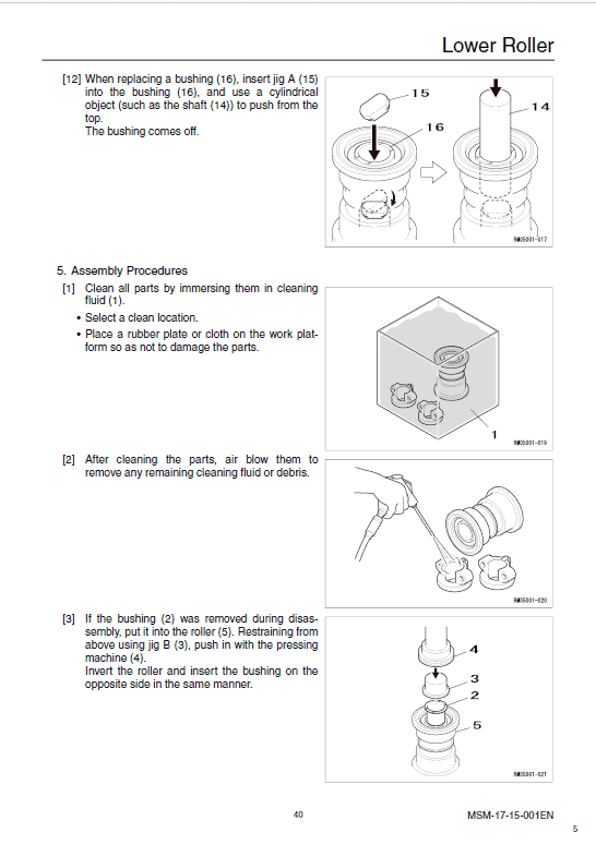
Lower Roller………………………………………………………………………………………………..20
1. Removal Procedure…………………………………………………………………………….21
2. Installation Procedure………………………………………………………………………….22
Center Joint ………………………………………………………………………………………………..23
1. Removal Procedure…………………………………………………………………………….24
2. Installation Procedure………………………………………………………………………….25
Upper Unit
Swing Unit ………………………………………………………………………………………………….26
Engine ……………………………………………………………………………………………………….30
Hydraulic Pump …………………………………………………………………………………………..33
Control Valve ………………………………………………………………………………………………35
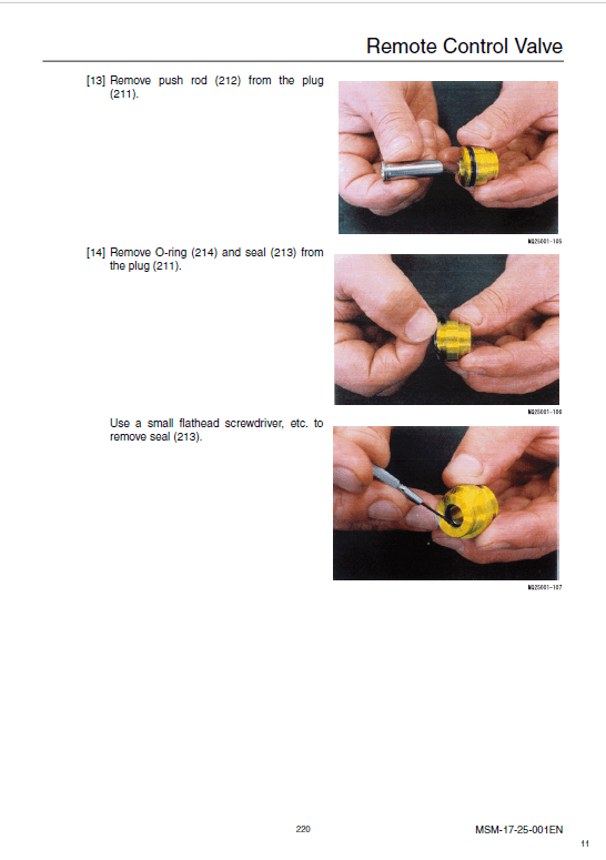
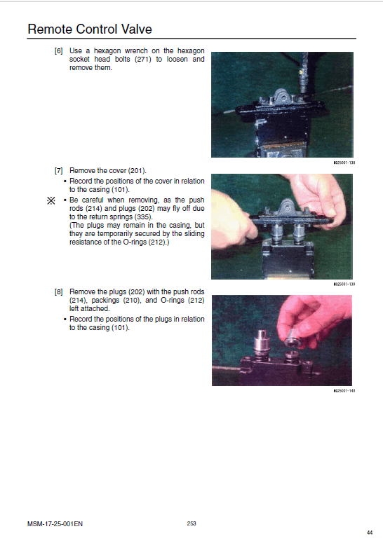
Remote Control Valve…………………………………………………………………………………..36
Operator Cab………………………………………………………………………………………………39
Reading Flow Charts …………………………………………………………………………………………………………………………. 1
Diagnostic Trouble Code Number and Problem ……………………………………………………………………………………. 1
Abbreviation Table ……………………………………………………………………………………………………………………………. 2
About Wiring Colors ………………………………………………………………………………………………………………………….. 3
Reading Block Diagrams……………………………………………………………………………………………………………………. 4
Reading Trouble Diagnosis………………………………………………………………………………………………………………… 6
Cautions for Maintenance ………………………………………………………………………………………………………………… 12
Electrical System…………………………………………………………………………………………………………………………….. 12
Fuel Injection System………………………………………………………………………………………………………………………. 12
How to Proceed with Trouble Diagnosis …………………………………………………………………………………………… 13
Trouble Diagnosis Procedure……………………………………………………………………………………………………………. 13
Inquiry …………………………………………………………………………………………………………………………………………… 14
Preliminary Inspection……………………………………………………………………………………………………………………… 16
Trouble Diagnosis …………………………………………………………………………………………………………………………… 16
Diagnostic Trouble Code Reading Procedure……………………………………………………………………………………… 18
Confirmation after Repair …………………………………………………………………………………………………………………. 19
Final Confirmation Items List…………………………………………………………………………………………………………….. 19
Diagnostic Trouble Code Deletion Method …………………………………………………………………………………………. 19
Injector Inspection Methods Using A Thermogun ………………………………………………………………………………… 20
Sorting Methods Using Noncontact Infrared Thermometer……………………………………………………………………. 27
Sorting methods……………………………………………………………………………………………………………………………… 27
Breaker Box Inspection Procedure ……………………………………………………………………………………………………. 28
Engine Control System…………………………………………………………………………………………………………………….. 31
Engine Control (common rail) System Functions and Operation Explanation ………………………………………….. 31
Engine Control Module (ECM) ………………………………………………………………………………………………………….. 39
Engine Component Parts Layout Diagram………………………………………………………………………………………….. 41
Engine Control Module (ECM) Wiring Diagram …………………………………………………………………………………… 59
Engine Control Module (ECM) Pin Layout ………………………………………………………………………………………….. 60
Engine Harness Routing Diagram……………………………………………………………………………………………………… 74
Connector List ………………………………………………………………………………………………………………………………… 78
Function Inspection List…………………………………………………………………………………………………………………… 80
Function Inspection List …………………………………………………………………………………………………………………… 80
Trouble Diagnosis by Service Support……………………………………………………………………………………………….. 81
Checking the Start Circuit System …………………………………………………………………………………………………….. 82
Checking the Start System……………………………………………………………………………………………………………….. 86
Checking the Fuel System……………………………………………………………………………………………………………….. 88
Checking the Suction Air System………………………………………………………………………………………………………. 92
Checking the Exhaust System ………………………………………………………………………………………………………….. 92
Checking the EGR Control System……………………………………………………………………………………………………. 93
Engine-side Trouble…………………………………………………………………………………………………………………………. 95
Engine-side DTC List ………………………………………………………………………………………………………………………. 95
Trouble Recovery………………………………………………………………………………………………………………………….. 103
Screen Display Details …………………………………………………………………………………………………………………… 104
Abnormality Display ………………………………………………………………………………………………………………………. 106
DTC: 0087 Abnormally Low Common Rail Pressure (supply pump not sending pressure)………………………. 107
DTC: 0088 Abnormally High Common Rail Pressure (1st stage or 2nd stage) ………………………………………. 113
DTC: 0089 Common Rail Pressure Abnormality (supply pump sending too much pressure) …………………… 117
DTC: 0090 SCV (suction control valve) Drive System Disconnection, +B Short, or GND Short………………… 121
DTC: 0107 Atmospheric Pressure Sensor Circuit Abnormality (abnormally low voltage)…………………………. 126
DTC: 0108 Atmospheric Pressure Sensor Circuit Abnormality (abnormally high voltage) ……………………….. 132
The Sumitomo Manual Preface
The purpose of this Sumitomo Excavator manual is to assist dealers and repair serviceman in efficient repair and maintenance of their machinery. Carrying out the procedures as detailed, together with the use of any special tools needed.
Using the Sumitomo SH135X-3B Manual
To make information easier to find, there is an index at the beginning of each section listing the various parts in that section. At the beginning of each part there is a table of contents which should also be used as a guide to locate information.
To assist with locating information, each section of the manual is preceded by a contents page listing the repair operations, Each instruction within an operating has a sequence number. To complete the operation in the minimum time is possible follow the manual guideline and repair instructions.
When parts have to be replaced in either the SH135X-3B Hydraulic Excavator , it is essential that only genuine Sumitomo parts should be used. Special attention should be paid to the following points concerning repairs and the fitting of replacement parts and accessories.
Indexing
For convenience the manual is divided into section and parts, each page bearing a section and part number. The sections are subdivided into numbered operation. This simplifies cross referencing and enable the subject to be found easily.
Be the first to review “Sumitomo SH135X-3B Hydraulic Excavator Repair Service Manual”
You must be logged in to post a review.
Reviews
There are no reviews yet.