Takeuchi TL150 Loader Service Manual
$36.00
Takeuchi TL150 Service Repair Manual – 828 Pages
Takeuchi TL150 Operating Manual – 196 Pages
Parts Manual – 573 Pages
Engine manual for TL150 4TNE106T-TBL – 130 Pages
- Description
- Reviews (0)
Description
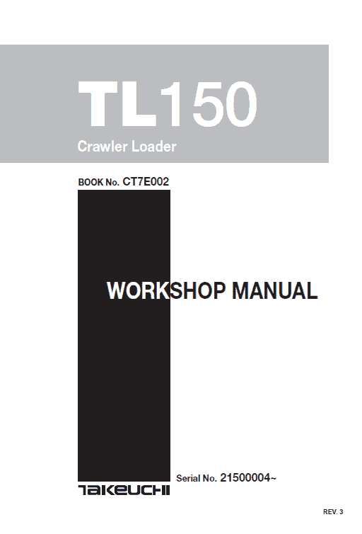
Takeuchi TL150 Compact Loader Service Manual
Type: Loader TL150
Format: PDF
Language of the Manual: English
Takeuchi TL150 Service Manual – 828 Pages
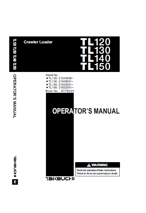
Takeuchi TL150 Operating Manual – 196 Pages
Parts Manual – 573 Pages
Engine manual for TL150 4TNE106T-TBL – 130 Pages
For All applicable S/N
The manual describes operation, service, repair and maintenance of the Loader, as well as safety instructions that should be follow.
The Takeuchi TL150 manual is intended for persons who engage in maintenance operations, and explains procedures for disassembly and reassembly of the machine, check and maintenance procedures, maintenance reference values, troubleshooting and outline specifications, etc. Please use this Takeuchi manual for Loader TL150 as a reference in service activities to improve maintenance techniques.
Please note that the contents and diagrams included in this manual may not match your machine exactly.
Items or diagram which manual contains are subject to change without notice due to design modifications, etc. Always store the Takeuchi Loader manual near at hand preferably on the machine itself. When transferring ownership of this machine, be sure to provide the owner manual to the next owner.
Table of Content of TL150 Instructions Manual:
I . GENERAL
II . SPECIFICATIONS
III. MACHINE CONFIGURATION
IV. HYDRAULIC UNITS
V . TROUBLESHOOTING
VI. ENGINE
Before operating, perform the prescribe inspections and make repairs immediately should any irregularities be found. If a failure that causes loss of control such as steering, service brakes or engine occurs, stop the machine motion as quickly as possible, follow the shutdown procedure, and keep machine securely park until the problem is fixed.
Extract from the Service Manual:
(1} Structural and functional outline
(1.1) Turbine
The exhaust gas from the engine is accelerated at the nozzle portion in the turbine housing and blown onto the turbine impeller to rotate the turbine shaft.
This is called the turbine. A seal ring and heat insulating plate are installed to prevent the bearing from adverse influence of the gas.
(1.2) Compressor
The compressor impeller installed on the turbine shaft rotates with the shaft to suck and compress air for feeding into the intake manifold.
This is called the blower or compressor.
(1.3) Bearings
• Thrust bearing:
As the turbine shaft is constantly applied with a thrust force, this bearing prevents the shaft from being moved by the thrust force.
• Radial bearing:
A floating bearing is adopted. Since the bearing moves with the turbine shaft as the oil films are formed both inside and outside the bearing, the bearing sliding speed is slow_er than the turbine shaft speed, resulting in higher dynamic stability.
(1.4) Compressor side sealing mechanism
To prevent the intake air and oil from leaking, a seal ring and a seal plate are provided to form a double wall structure on the rear side of the compressor impeller.
(1.5) Waste gate
When the blower side pressure (intake air pressure) exceeds the specified level, the exhaust gas at the turbine inlet is partially bypassed to the exhaust discharge side to control the turbine rpm so as to maintain the intake pressure at the specified level for improving the response to load variation in the low to medium speed range and to minimize black smoke generation.
It consists of a control assembly separated from the turbocharger and a valve assembly installed in the turbine impeller chamber.
Be the first to review “Takeuchi TL150 Loader Service Manual”
You must be logged in to post a review.






Reviews
There are no reviews yet.