

John Deere 643D Feller Buncher Service Manual
$50.00
Language: English
Format: PDF
Publication: TM1481 & TM1482
Applicable: Feller Buncher Model 643D
- John Deere 643D Feller Buncher Harvester Repair Manual – 798 Pages (TM1482)
- John Deere 643D Feller Buncher Harvester Operation and Test Manual – 850 Pages (TM1481)
- Description
- Reviews (0)
Description
John Deere 643D Feller Buncher Harvester Repair Manual
Language: English
Format: PDF
Publication: TM1481 & TM1482
Applicable: Feller Buncher Model 643D
- John Deere 643D Feller Buncher Harvester Repair Manual – 798 Pages (TM1482)
- John Deere 643D Feller Buncher Harvester Operation and Test Manual – 850 Pages (TM1481)
Table of Content of the John Deere Harvester 643D
Repair Manual
Group 0001—Safety Information
Group 0002—General Specifications
Group 0003—Torque Values
Group 0004—Fuels And Lubricants
SECTION 01—Wheels
Group 0110—Powered Wheels And Fastenings
SECTION 02—Axles And Suspension System
Group 0200—Removal And Installation
Group 0225—Input Drive Shafts And U-Joints
SECTION 03—Transmission
Group 0300—Removal And Installation
Group 0315—Control Linkage
Group 0350—Gears, Shafts, Bearings, And Power Shift Clutch
Group 0360—Hydraulic System (Hydrostatic Transmission)
SECTION 04—Engine
Group 0400—Removal And Installation
SECTION 05—Engine Auxiliary Systems
Group 0505—Cold Weather Starting Aids
Group 0510—Cooling System
Group 0515—Speed Controls
Group 0520—Intake System
Group 0530—External Exhaust System
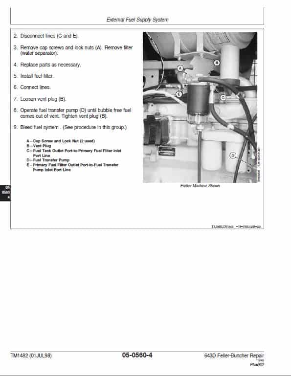
Group 0560—External Fuel Supply System
SECTION 07—Dampener Drive
Group 0752—Elements
SECTION 08—Splitter Drive (Pump Drive Gearbox)
Group 0800—Removal And Installation
Group 0851—Gears, Shafts And Bearings
SECTION 09—Steering System
Group 0960—Hydraulic System
SECTION 10—Service Brakes
Group 1011—Active Elements
Group 1060—Hydraulic System
Group 1111—Active Elements
Group 1115—Controls Linkage
SECTION 16—Electrical System
Group 1671—Batteries, Support And Cables
Group 1672—Alternator, Regulator And Charging System Wiring
Group 1674—Wiring Harness And Switches
Group 1676—Instruments And Indicators
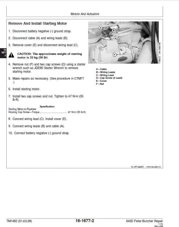
Group 1677—Motors And Actuators
SECTION 17—Frame Or Supporting Structure
Group 1740—Frame Installation
Group 1746—Frame Bottom Guards
SECTION 18—Operator’s Station
Group 1800—Removal And Installation
Group 1810—Operator’s Enclosure
Group 1821—Seat And Seat Belt
Group 1830—Heating And Air Conditioning
SECTION 20—Safety, Convenience And Miscellaneous
Group 2003—Fire Extinguisher
Group 2004—Horn And Warning Devices
SECTION 21—Main Hydraulic System
Group 2160—Hydraulic System
SECTION 39—Shear
Group 3901—Blades And Cutting Elements
Group 3915—Controls Linkage
Group 3960—Hydraulic System
Group 9900—Dealer Fabricated Tools
Group 01—Safety Information
Group 02—General Specifications
Group 03—Torque Values
Group 04—Fuels And Lubricants
Section 9005—Operational Checkout Procedure
Group 10—Operational Checkout Procedure
Section 9010—Engine
Group 05—Theory Of Operation
Group 10—System Operational Checks
Group 15—Diagnostic Information
Group 20—Adjustments
Group 25—Tests
Section 9015-2—Electrical System (Serial No. —788773)
Group 00—Electrical Operation And Test
Section 9015-1—Electrical System (Serial No. 788774—)
Group 05—System Information
Group 10—System Diagrams
Group 15—Sub-System Diagnostics
Group 20—Adjustments And Additional Information
Section 9020—Power Train
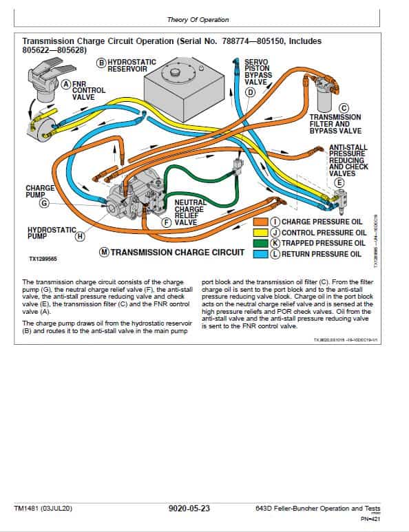
Group 05—Theory Of Operation
Group 15—Diagnostic Information
Group 20—Adjustments
Group 25—Tests
Section 9025—Hydraulic System
Group 05—Theory Of Operation
Group 15—Diagnostic Information
Group 20—Adjustments
Group 25—Tests
Section 9031-2—Heating And Air Conditioning (Serial No. —788773)
Group 05—Theory Of Operation
Group 10—System Operational Checks
Group 15—Diagnostic Information
Group 20—Adjustments
Group 25—Tests
Components are well shielded and have hinged or removable panels to allow for easy access for all routine inspection and servicing by the operator. Service personnel can service or remove small components through these panels. Virtually all external engine servicing and attachment repair or replacement can be completed by opening the top and side hinged engine enclosure doors. This includes the alternator, water pump, starter, A/C compressor, turbocharger, fuel injection pump and injectors. Rear panels allow access to the hydraulic valve compartment, the fuel/water separator and the pumps. A front panel provides access to the radiator, the oil cooler and the air conditioning condenser.
Read the safety messages in the introduction of this manual and the cautions presented throughout the text of the manual.
The John Deere 643D Feller Buncher Harvester Repair Manual sections tell how to repair the components and help you identify the majority of routine failures quickly.
Information is organized in groups for the various components requiring service instruction. At the beginning of each group are summary listings of all applicable essential tools, service equipment and tools, other materials needed to do the job, service parts kits, specifications, wear tolerances, and torque values.
Technical Manuals are concise guides for specific machines. They are on-the-job guides containing only the vital information needed for diagnosis, analysis, testing, and repair.
Be the first to review “John Deere 643D Feller Buncher Service Manual”
You must be logged in to post a review.

Reviews
There are no reviews yet.