
Case DX23, DX26 Tractor Service Manual
$34.00
Case DX23, DX26 Tractor Service Manual – 708 Pages
Publication Number: 87367148
English
August 2005
Format: PDF
- Description
- Reviews (0)
Description
Case DX23, DX26 Tractor Manual
Tractor Model: DX23, DX26
Publication Number: 87367148
English
August 2005
Format: PDF
Case DX23, DX26 Tractor Service Manual – 708 Pages
Manual Table of Content:
SECTION 00 – GENERAL INFORMATION . . . . . . . . . . . . . . . . . . . . . . . . . . . . . . 2
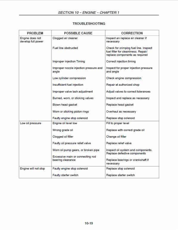
SECTION 10 – ENGINE . . . . . . . . . . . . . . . . . . . . . . . . . . . . . . . . . . . . . . . . . . . . . . 3
SECTION 18 – SINGLE CLUTCH . . . . . . . . . . . . . . . . . . . . . . . . . . . . . . . . . . . . . . 10
SECTION 21 – TRANSMISSION . . . . . . . . . . . . . . . . . . . . . . . . . . . . . . . . . . . . . . . 11
SECTION 25 – FWD FRONT AXLE . . . . . . . . . . . . . . . . . . . . . . . . . . . . . . . . . . . . 13
SECTION 27 – DIFFERENTIAL, REAR AXLE . . . . . . . . . . . . . . . . . . . . . . . . . . . 14
SECTION 29 – HYDROSTATIC TRANSMISSION . . . . . . . . . . . . . . . . . . . . . . . . 15
SECTION 31 – POWER TAKE-OFF (PTO) . . . . . . . . . . . . . . . . . . . . . . . . . . . . . . 19
SECTION 33 – BRAKES . . . . . . . . . . . . . . . . . . . . . . . . . . . . . . . . . . . . . . . . . . . . . . 20
SECTION 35 – HYDRAULIC SYSTEM . . . . . . . . . . . . . . . . . . . . . . . . . . . . . . . . . . 21
SECTION 41 – STEERING . . . . . . . . . . . . . . . . . . . . . . . . . . . . . . . . . . . . . . . . . . . . 24
SECTION 44 – WHEELS AND TIRES . . . . . . . . . . . . . . . . . . . . . . . . . . . . . . . . . . 25
SECTION 55 – ELECTRICAL SYSTEM . . . . . . . . . . . . . . . . . . . . . . . . . . . . . . . . . 26
SECTION 90 – PLATFORM . . . . . . . . . . . . . . . . . . . . . . . . . . . . . . . . . . . . . . . . . . . 32
The following pages are the collation of the contents pages from each section and chapter of the DX23, DX26 Repair manual. Complete Repair Manual# 87367148
Manual Extract: CYLINDER HEAD AND VALVE TRAIN COMPONENTS
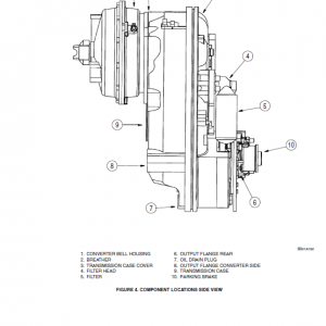
The cylinder head incorporates the valve assemblies, rocker arms, rocker shaft, push rods, lifters, and pre-combustion chambers. The air intake manifold is incorporated into the left hand side of the valve cover assembly. The exhaust manifold is bolted on the left-hand side of the cylinder head. The cylinder heads have integral valve guides. Standard size valves only are used. Figure 2 provides a cut-away front and side view of an engine.
A pre-combustion chamber is located between the injector assembly and the combustion chamber of the cylinder and provides an area for initial ignition of the fuel for improved starting. A glow plug located in the head extends into the pre-combustion chamber and, when energized, pre-heats the fuel-air mixture for improved fuel ignition under cold weather conditions.
Be the first to review “Case DX23, DX26 Tractor Service Manual”
You must be logged in to post a review.
Reviews
There are no reviews yet.