
Case D25, D29, D33 Tractor Service Manual
$34.00
Case D25, D29, D33 Tractor Service Manual – 768 Pages
Publication Number: 84132131
English
October 2008
Format: PDF
- Description
- Reviews (0)
Description
Case D25, D29, D33 Tractor Manual
Tractor Model: D25, D29, D33
Publication Number: 86619354
English
Format: PDF
Case D25, D29, D33 Tractor Service Manual – 615 Pages
Manual Table of Content:
SECTION 00 — GENERAL INFORMATION
SECTION 10 — ENGINE
SECTION 18 — CLUTCH
SECTION 21 — TRANSMISSION
SECTION 25 — 4WD FRONT AXLE
SECTION 27 — DIFFERENTIAL AND REAR AXLE
SECTION 29 — HYDROSTATIC TRANSMISSION
SECTION 31 — POWER TAKE-OFF SYSTEMS
SECTION 33 — BRAKES
SECTION 35 — HYDRAULIC SYSTEM
SECTION 41 — STEERING
SECTION 44 — 2WD FRONT AXLE
SECTION 55 — ELECTRICAL
This repair manual provides the technical information needed to properly service the Case IH D25, D29 and D33 tractors. Use this manual in conjunction with the operator’s manual for complete operation, adjustment, and maintenance information.
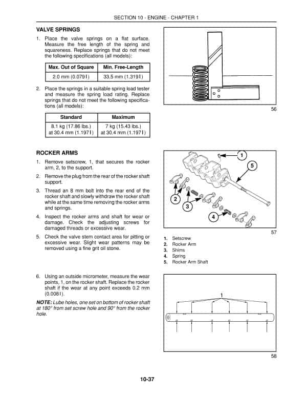
Manual Extract: CYLINDER HEAD AND VALVE TRAIN COMPONENTS
The cylinder head incorporates the valve assemblies, rocker arms, rocker shaft, push rods, and lifters. A swirl chamber located between the injector assembly and the main combustion chamber of the cylinders provides improved starting and greater fuel efficiency. Initial combustion starts in the pre combustion chamber and as the expansion occurs a strong swirl pattern is created in the main combustion chamber for more complete combustion of the air-fuel mixture. The air intake manifold is separate from the cast aluminum valve cover on all these engines. The exhaust manifold is bolted on the left-hand side of the cylinder head on each of the models. Cylinder heads have integral valve guides. Standard size valves only are used.
CYLINDER BLOCK ASSEMBLY
The cylinder block assembly contains the pistons, connecting rods, crankshaft, timing gears, and engine oil pump. The crankshaft is supported on four main bearings. The front bearing is positioned in a bore in front of the block. The second, third, and fourth bearings are split liners located in holders bolted to the block. The camshaft is supported on two ball bearings located on each end of the block.
Be the first to review “Case D25, D29, D33 Tractor Service Manual”
You must be logged in to post a review.
Reviews
There are no reviews yet.